Blog
Recirculation and Hot-Spot Bypass in Fan Arrays

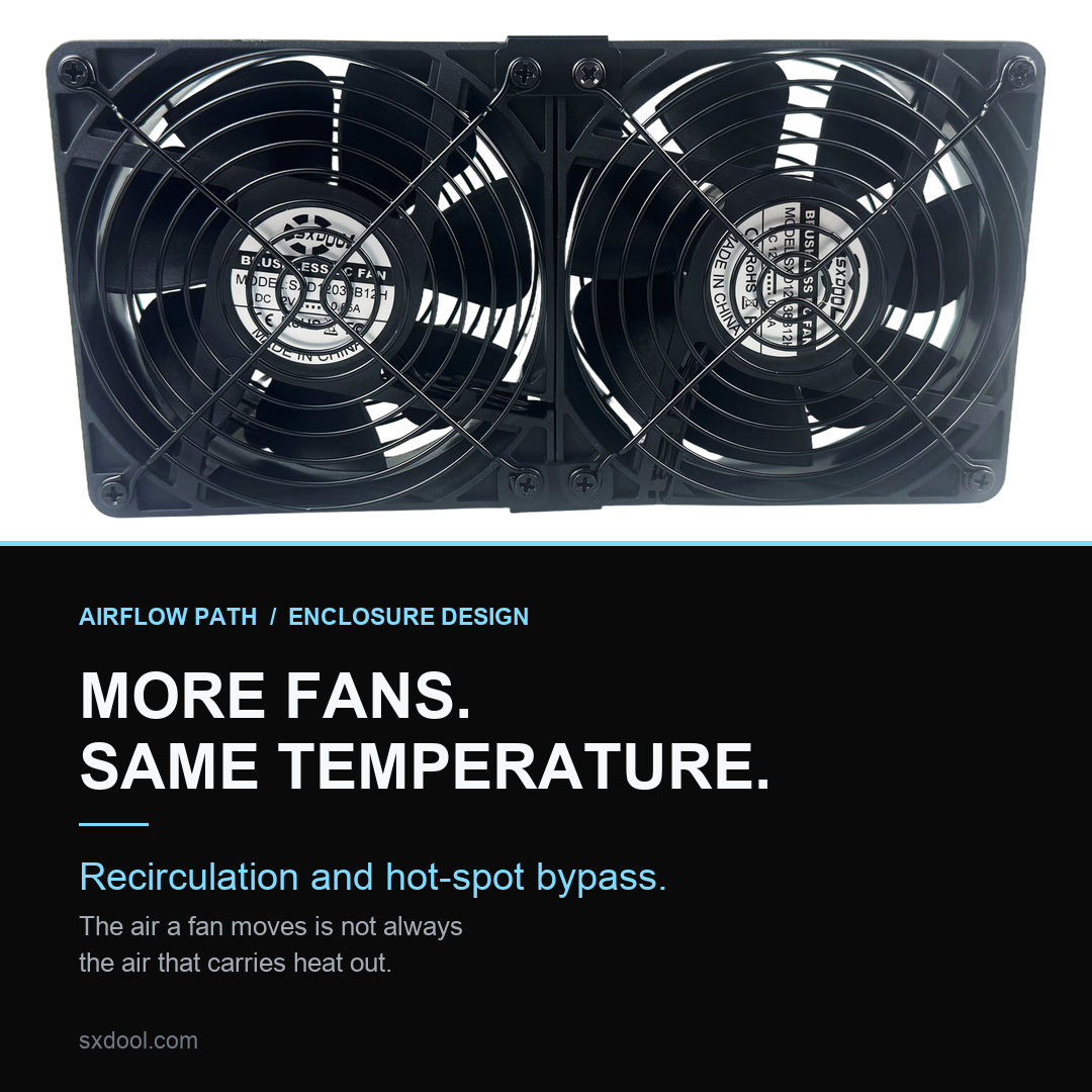
Adding a fan raises the quantity of air the fans move. It does not
automatically raise the quantity of air that carries heat out of the box. Those
are two different measurements, and in a crowded enclosure the gap between them
has a shape: a route along which air the fans have already pushed out finds its
way back in, or a route along which air the fans did pull in crosses the
enclosure without passing anything hot.
Both failures look the same from outside. The fan spins, the current draw is
unremarkable, the sound is what you expect, and the temperature does not move.
The purchase order records an increase in airflow. The sensor records nothing at
all.
1. The reflex, and why it is reasonable
The reflex is correct in the abstract. A hot enclosure needs more air moving
through it, and the cheapest way to move more air is to add a fan or fit a faster
one. This is why the reflex survives: it works often enough to be trusted, and
when it fails the failure is quiet rather than dramatic, so nobody goes back and
audits the assumption.
The assumption is that the air a fan moves and the air an enclosure processes
are the same air. They are the same air only when the enclosure has one opening
for intake, one opening for discharge, and nothing else. Almost no real enclosure
satisfies that. Cable entries, unused knockouts, panel seams, filter frames that
do not seat, the gap between a fan and the sheet metal it is screwed to — each is
an opening, and each opening is a candidate return path. The mirror question — what
happens when the intended intake path is itself restricted — is covered in
installation
effects on inlet clearance and guard geometry; this article assumes the intake is
open and asks where the air goes once it is inside.
2. Two quantities that are easy to confuse
Call the first quantity delivered airflow: the volume a fan passes
through its own aperture per unit time, at whatever pressure the installation
happens to impose. It is a property of the fan and its operating point, and it is
the quantity a datasheet curve describes. Reading that curve, and reading where it
intersects the impedance of the installation, are the two skills this argument
depends on: see
reading
airflow against pressure and
calculating
system impedance.
Call the second useful through-flow: the portion of that delivered
airflow which enters cold, crosses the surfaces that need cooling, and leaves
warm. This is the only quantity that removes heat. It is not on any datasheet,
because it depends on geometry the fan manufacturer has never seen.
Heat removal scales with useful through-flow, not with delivered airflow. A
fan can increase the first while leaving the second unchanged, or in unlucky
cases reduce it. Recirculation and hot-spot bypass are the two mechanisms by which
that happens, and they are opposites: recirculation wastes air that never gets
in, bypass wastes air that gets in and never does anything.
3. Route one: around the flange
The most common return path is the shortest one. A fan pulls air through a
cutout in a panel. The pressure on the discharge side is above ambient; the
pressure on the intake side is below it. The sheet metal between the two is
therefore a barrier standing between a high-pressure region and a low-pressure
region, and every imperfection in that barrier is a leak driven by exactly the
pressure difference the fan worked to create.
Air escaping around the flange does not travel far. It leaves the discharge
side at the perimeter, turns, and re-enters the intake a few millimetres away.
The fan then moves it again. From the fan’s point of view nothing is wrong; it is
delivering its curve. From the enclosure’s point of view the same parcel of air
has been processed repeatedly and has carried away almost nothing, because it
never went anywhere.
This is why a fan mounted on a thin panel with four screws and no gasket can
read as healthy on every instrument available while cooling nothing. The tell is
not the fan. The tell is that the discharge stream feels weak and diffuse at the
point where it should be concentrated, and that air near the intake is warmer
than the room.
4. Route two: between the fans in a bank
Put two or more fans side by side in a shared plenum — the arrangement discussed
in integrated
fan arrays and airflow density — and a second class of
return path appears. Fans are not perfectly matched. They differ in speed, in
blade tolerance, in how much of their aperture is obstructed by a guard or a
finger grille, and in how close each sits to the nearest obstruction. One of them
will be running at a slightly higher discharge pressure than its neighbour.
If they share an intake volume, that difference does work. The stronger fan
raises the pressure in the shared space; the weaker fan’s intake is the lowest
pressure available; the strongest available path between them is the gap they
share rather than the long route through the enclosure. The bank begins to
recirculate internally, fan to fan, instead of drawing fresh air through the
intake.
The symptom is specific and worth memorising: the array as a whole moves a
great deal of air, the combined noise is high, and the enclosure temperature sits
where it sat before the second fan was fitted. Adding a third fan makes it worse
rather than better, because each addition adds another pressure source into the
same shared volume.
The fix is not a bigger fan. It is to stop the bank from sharing a volume: a
divider between fans, a partitioned intake plenum with one path per fan, or a
baffle that forces each fan’s intake to reach outside the shared space. Once each
fan owns its own path, the pressure difference between neighbours has nowhere to
drive flow, and the interference disappears.
5. Route three: through the enclosure itself
The third route is the one people find hardest to accept, because it is not
near the fan at all. A perforated cable gland, a seam that was never sealed, an
unused knockout with a plastic plug that has gone brittle, a door gasket that has
taken a set — these connect the discharge region to the intake region just as
effectively as a missing flange gasket, only further away and therefore less
suspicious.
This route is worth checking first for a practical reason: it is cheap to
close and it is often the whole answer. A sealed enclosure with one intake and
one discharge turns a fan from a stirrer into a pump. The same fan, unchanged,
moves the same delivered airflow but a far larger share of it becomes useful
through-flow, because there is nowhere else for it to go.
6. The mirror failure: hot-spot bypass
Hot-spot bypass is the opposite error and it is easier to miss, because
everything about it looks correct. Air enters through the intake, as intended. It
leaves through the discharge, as intended. There is no leak. The fans are moving
the volume the specification asked for.
What the air did in between was take the shortest available route from intake
to discharge, and the shortest route through a box is almost never the route
through the dense part. Air behaves like current in a parallel circuit: it divides
in inverse proportion to the impedance of each branch, and the branch with the
clear space around the heat sink is not the branch that needs the cooling. The
volume takes the open corridor. The dense region — the fin stack, the winding, the
component that actually runs hot — sits in a stagnation zone with air on all sides
of it and none through it.
This is the mechanism behind the single most frustrating report in enclosure
cooling: the average air temperature inside the box fell when fans were added,
and the component that was overheating did not. Both readings are true. The fans
improved the bulk air. They did not touch the local one.
Bypass gets worse as you add capacity, which is the counter-intuitive part.
Every fan added to an open interior lowers the impedance of the easy corridor, and
lower impedance on the easy branch pulls a larger share of the total into that
branch. The dense region’s share falls. This is why an array can be doubled in
capacity and show a hotter hot spot than before.
7. Why an extra fan can make the reading worse
Three effects push in the same direction, and any one of them is enough to
neutralise the gain from the added airflow.
The first is the shared-plenum interference described above: the new fan
creates a new pressure difference inside the box, and part of the air it moves is
air another fan already moved.
The second is added heat. A fan is not thermally free. Its motor losses end up
in the airstream it is pushing, and in a small sealed enclosure that contribution
is not negligible relative to what the electronics dissipate. Every added fan
raises the floor.
The third is the shift in operating point. Fitting an additional fan into an
existing opening, or replacing one fan with two in the same space, changes the
system impedance the remaining fans see. When impedance rises — and blocking part
of an aperture with a second fan body does raise it — each fan slides up its curve
toward higher pressure and lower flow. The array can end up passing less air than
the single fan it replaced, while consuming more power and making more noise.
8. Diagnosis: what to measure, and what a real answer looks like
The useful diagnostic is not a single temperature. It is a set of readings
taken at positions that distinguish path from source.
Measure the intake air temperature just outside the enclosure, and the
discharge air temperature just outside it. A working arrangement shows a clear
rise between them, because heat has been picked up. The pressure argument behind
that reading is set out in
why
static pressure matters in dense racks. A recirculating arrangement
shows a small rise and a warm intake, because the intake is partly the discharge
returning.
Measure at the hot spot and at a point in the open volume. A large difference
means the bulk air is being handled and the local path is not — bypass. A small
difference with a high absolute reading means the air itself is not being
replaced — recirculation or insufficient exchange.
Then run the parity test, which costs nothing and settles most arguments. Swap
the positions of two fans in the bank and re-measure. If the hot spot moves with
the fan, the problem is the fan. If the hot spot stays exactly where it was, the
problem is the path, and no fan will fix it.
Finally, run the subtraction test. Remove or blank off the newest fan and
re-measure. If the reading does not change, the fan was never contributing useful
through-flow. That result is not a failure of the fan; it is a measurement of the
enclosure.
9. The order of operations
The sequence matters more than any individual step, because doing them out of
order produces a false negative that is expensive to unwind.
Seal first. Gaskets at every fan flange, blanking plates over
unused openings, sealed cable entries, a door gasket that actually compresses.
This raises the impedance of every return path to something well above the
impedance of the intended path. Note what happens to the fan when you do this: it
moves up its curve toward higher pressure, so delivered airflow falls. That is not
a regression. Useful through-flow rises, and the delivered figure was never the
one that mattered.
Partition second. Give each fan its own intake path, or a
divider that prevents neighbours from sharing a volume. Separate the intake
plenum from the discharge plenum by something more substantial than proximity.
Direct third. Where bypass is the problem, the fix is a baffle:
a physical obstruction that closes the easy corridor and forces air through the
dense region. This deliberately raises impedance on the branch that should not be
carrying flow. In ducted and racked systems the same idea appears as blanking
panels and containment — the principle is identical, only the scale differs. For the
failure-tolerance side of array design, which is a different problem from path
control, see
redundant
fan configurations for mission-critical racks and
hot-aisle
and cold-aisle containment.
Balance fourth. In a bank of fans, matched units or
independent speed control stop one fan from dominating the shared volume. A single
speed command to mismatched fans recreates the pressure imbalance that started the
whole problem.
Add capacity last. Only once the path is clean does an
additional fan translate into additional heat removal. Before that point, an
additional fan translates into additional power, additional noise, and
occasionally a worse hot spot.
10. What this changes when you specify
Three practical consequences follow, and they apply to buyers as much as to
designers.
First, a quotation that answers a thermal problem with a larger airflow figure
has not answered the thermal problem. The question to ask is what the enclosure
looks like at the intake and at the discharge, and whether either of them shares a
volume with the other. A supplier who asks that question is worth more than one
who quotes a curve.
Second, the fan is rarely the limiting component in a badly sealed enclosure,
and specifying a higher-grade fan to compensate is paying for capability the
installation discards. The same money spent on sealing and partitioning usually
returns more, and it returns it at the level of every fan in the bank rather than
one.
Third, and most useful in practice: when a design has a hot spot, the
specification that resolves it is usually geometric rather than aerodynamic.
Where the air enters, where it is forced to go, and where it leaves are decisions
made on the enclosure drawing. The fan’s job is to supply the pressure that makes
those decisions work. Asking a fan to compensate for a path that does not exist is
the origin of most of the disappointing arrays in service today.
Recirculation and bypass are not fan defects and they are not installation
errors in the sense of something assembled wrongly. They are the predictable
consequence of an enclosure that has more than one path between its high-pressure
and low-pressure regions, and of a dense region that offers more impedance than
the space around it. Both are visible before the first fan is ordered, in the
geometry, if anyone looks.
If you are specifying an array for an enclosure that already exists, send us the
intake and discharge arrangement along with the thermal target. The
RFQ guide lists what we need
to answer the path question rather than only the airflow question.