Blog
AV Power Amplifier Cooling Fans: Airflow, Noise and Rack Heat

For an OEM AV power amplifier, select the cooling fan against the complete air path, heat loss and listening-room noise limit. The fan must move enough air through the assembled chassis at the required operating conditions, start reliably with the amplifier’s supply and control circuit, and avoid exhausting hot air into another unit’s intake. A matching frame size alone does not establish suitability.
This guide covers internal electronics cooling for professional power amplifiers and their racks. Projector light engines and optical assemblies require a separate thermal design. The SXDOOL candidate below is a starting point for a specific shallow electronics compartment; it is not a tested replacement for any amplifier manufacturer’s original fan.
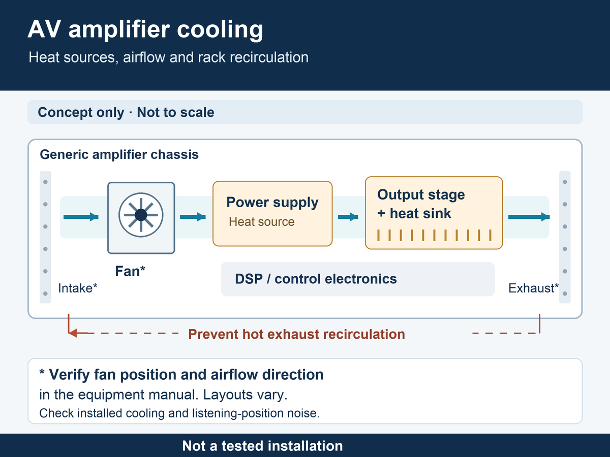 Open diagram at full size
Define the heat sources and the operating duty
Map the output-stage heat sinks, power-supply switching devices and magnetics, and any DSP or control-electronics compartment. Identify which parts share a cooling stream and which receive air already warmed by another section. Measure the relevant component temperatures with the covers fitted. A comfortable exhaust-air temperature does not establish that every internal hot spot is controlled.
Do not use the amplifier’s advertised audio output power as its heat load. Obtain loss data or measure the electrical and thermal behavior for the intended speaker load, driven channels and signal duty. The Q-SYS CX-Q hardware manual, revision TD-001661-01-C, separates heat loss and current draw by operating condition. Its figures describe those amplifiers, not the cooling requirement of a different design.
Define at least a quiet operating condition and a sustained demanding condition. A conference room with long silent intervals, background-music installation and continuously driven venue system can place different demands on the same chassis. Include the specified inlet temperature and expected supply variation when defining the sample test.
Match the fan to the chassis and the rack airflow
Draw the route from the room or rack intake, through the fan and heat-generating components, to the final exhaust. Include the grille, filter if fitted, heat-sink channels, cable bundles and rack door. The required airflow must be available against this combined resistance; a free-air flow rating cannot establish the operating point.
Check every unit’s airflow direction before arranging a mixed rack. Yamaha’s PC-D/DI panel manual identifies a front cooling intake and rear exhaust, while the CX-Q manual specifies air moving from the sides/rear toward the front. Neither direction is a universal rule for AV equipment.
Look for a path that lets hot exhaust return to an intake, particularly behind a closed rack door or beside a shallow cabinet. Correct that route before trying to solve the problem with more fan speed. Preserve the equipment manufacturer’s required ventilation clearances; an unused rack space is not, by itself, evidence of an effective cooling path.
Resolve acoustic and electrical requirements together
A fan that passes the hottest thermal test can still be unsuitable near a microphone or listening position. Agree where noise will be measured, the background conditions and whether idle noise, steady fan noise or changes in fan speed are the limiting concern. Evaluate the installed fan with its actual grille and mounting, including audible vibration and tonal sound.
Fixed-speed operation offers a simple control arrangement but must meet both the thermal and acoustic limits at that speed. Variable-speed control needs a defined start-up command, minimum stable operation and response to temperature changes. Check behavior when the amplifier is already warm, when it returns from standby, and after a fault clears.
Before selecting a controlled fan, obtain the exact supply range, start-up current requirement, connector and pin assignment, and any control or feedback electrical definition. PWM control, speed feedback and a rotation-detection output serve different purposes. Do not infer the interface from the number of wires or connect an unspecified signal to the amplifier controller.
A limited SXDOOL candidate for a shallow electronics compartment
The SXDOOL 12012 slim axial platform is worth evaluating when a shallow auxiliary-electronics compartment has room for a nominal 120 × 120 mm fan plane and an axial air path. The published platform is 120 × 120 × 12 mm; the product page identifies its photographed 12 V sample as SXD12012S12M.
The reason to shortlist this candidate is its shallow frame. That does not establish low noise, sufficient pressure through a dense main heat sink, or compatibility with a speed-control circuit. A 120 mm fan plane is not a general fit for a 1U amplifier’s front or rear panel. Check mounting orientation, drawing, guard, inlet clearance and harness space in the complete assembly.
For SXD12012S12M, request the configuration-matched curve, current, acoustic test conditions and wiring definition before sample approval. Confirm environmental limits, bearing specification, life-test conditions and any required compliance evidence separately. The family page’s 5 V, 12 V and 24 V choices are separate configurations, not one universal-input model. No amplifier fit or performance result is claimed here.
If the main heat-sink tunnel is restrictive, the required fan plane is smaller, or the controller needs a specific PWM/feedback interface, supply those constraints for a different candidate review. Do not substitute the slim fan simply because it frees installation depth.
Approve the complete amplifier, not an isolated fan
Thermal protection must remain functional, but recurring protection events at the intended operating duty indicate that the design or operating conditions need review. For example, Yamaha’s PC-D/DI specifications describe thermal limiting and muting for the amplifier section. Such protection behavior is equipment-specific and is not a substitute for thermal qualification.
- Record the configuration. Identify the amplifier revision, exact fan and harness, speaker-load equivalent, channels driven, test signal, mains supply, rack arrangement and inlet temperature.
- Test the actual restriction. Fit the intended covers, grilles, filters and cable routes. Check component temperatures until the agreed stabilization criterion is reached, then record temperatures, fan behavior and output behavior together.
- Check transitions and noise. Test cold start, warm restart, standby recovery and the specified quiet operating condition. Assess noise at the agreed listening or microphone position as well as at the equipment.
- Review maintenance and failure response. Define access for filter or vent cleaning. Have the responsible equipment engineer verify the approved fan-fault and protection procedure; retain the amplifier’s original safety functions.
AV amplifier cooling questions
Can a quieter fan replace the original amplifier fan?
Acoustic improvement alone is insufficient. A replacement can change airflow under restriction, start-up behavior or the controller’s fault detection. Follow the amplifier manufacturer’s service requirements. This guide supports OEM design evaluation and does not approve a service replacement.
Should all amplifiers in a rack exhaust toward the rear?
Check the documentation for each unit. Real amplifier designs use different directions. Arrange the rack so that each unit receives suitable intake air and another unit’s exhaust does not recirculate into it.
Does a slim 12012 fan solve a noisy high-power heat-sink tunnel?
Not on the evidence of frame depth. SXD12012S12M is only a candidate for the shallow compartment described above. A high-resistance heat-sink tunnel requires a matched pressure-flow curve and installed thermal and acoustic measurements before a fan can be approved.
Send the amplifier cooling conditions for review
Include the available fan envelope and drawing, supply and control interface, loss estimate or measured temperatures, air-path sketch, speaker load and signal duty, highest expected inlet temperature, noise measurement position and sample quantity. State whether you are evaluating SXD12012S12M for a shallow auxiliary compartment or need another configuration for the main heat sink.
Request an AV amplifier cooling review
For a different equipment environment, see the stage-lighting cooling guide. Its optical, fixture-position and duty requirements need their own assessment.