Blog
Rack Server Cooling Fans: Chassis Airflow and Control

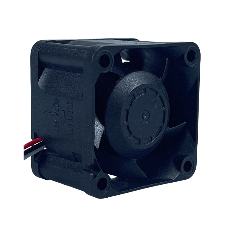
Choose a rack server fan for the populated chassis, its airflow resistance and its management controller—not for a free-air CFM number or the rack-unit height alone. Cooling must reach the processor heat sinks, memory and expansion devices under the intended workload. A proposed SXDOOL fan remains a candidate until its released documentation, interface and installed thermal results match the design.
This guide concerns fans inside an OEM rack server chassis. For ventilation around complete equipment, see server cabinet cooling; for drive-cage and disk-temperature questions, see NAS and storage enclosure cooling. For an existing branded server, use its approved fan assembly and service instructions.
Map the heat sources and the air path together
Start with the supported processor, DIMM, drive, backplane, riser, network-adapter and accelerator population. Draw the intended path from the chassis inlet through the fan bank and each component zone to the exhaust. Record the actual fan location; an array behind the front drives can face different restrictions from a rear-mounted fan or a dedicated riser fan.
Check processor heat sinks, voltage-regulator cooling, memory channels and the rear expansion area separately. A satisfactory CPU reading does not establish enough airflow at a network card, drive controller or memory module. Power supplies may have their own air path and control, so include their specified cooling behavior in the system review.
Equipment configurations can require different cooling hardware. Dell’s PowerEdge R650 cooling specifications tie the supported fan modules to the processor, drive, GPU and memory configuration, with a fan blank required in certain single-processor configurations. This illustrates configuration-dependent selection; it does not establish an SXDOOL replacement for a Dell module.
Use installed pressure–airflow data, not a size-based pressure table
The bezel, drive cage, backplane openings, heat-sink fins, cable routing, air shrouds and outlet grille form the cooling path. Identify where air can bypass a hot component instead of passing through it. Retain the intended cover, blanks and baffles during qualification; an open chassis is a different airflow arrangement.
Specify the airflow needed through the critical zones and characterize resistance for the actual build. Compare that requirement with the exact fan’s pressure–airflow curve at the proposed control setting and test conditions. Maximum airflow and shutoff pressure are separate endpoints. Neither endpoint proves that the installed operating point supplies the hottest component.
The rack-unit height limits space, but it does not prescribe a universal pressure, fan count or fan performance. Check the complete mounting envelope, holes, cable exit, connector, inlet clearance and flow direction. When a larger fan or a different duct appears attractive, verify that it fits the intended chassis rather than assuming that a nominal frame can be adapted.
A useful equipment-specific example is the Intel SR2500AL Technical Product Specification, revision 1.6, November 2008, section 3. Its cooling system includes fan modules, power-supply fans, baffles, a CPU duct and drive population. This historical example supports assessing the full cooling assembly; its component choices and limits are not specifications for a current server.
Define what the controller must detect and command
Before proposing a fan, obtain the chassis controller’s electrical interface: supply range, startup-current allowance, pin assignment, connector and required control and feedback functions. Specify PWM input levels and behavior, any tachometer pulse requirements, and the exact alarm states and timing. Wire color, pin count and a matching connector shell do not establish compatibility.
An RPM feedback output and a stopped-rotor alarm serve different purposes. If the baseboard management controller (BMC) expects speed pulses, an alarm-only signal cannot simply be substituted. Define behavior at startup, minimum command, loss of control, commanded stop and restart. Confirm how the controller recognizes a fan fault and what thermal response follows it; do not silence an alarm to make a mismatched fan appear acceptable.
Treat redundancy and hot swap as separate system requirements
Write down whether the failure being evaluated is one rotor, one fan body, one complete removable module or a shared electrical path. These are different faults. The remaining cooling paths must keep the specified components within their limits for the required workload and inlet conditions, with the intended controller response.
Lenovo’s ThinkSystem SR630 V2 fan rules explicitly describe N+1 redundancy in terms of one fan rotor. That model-specific statement should not be widened into permission to remove any complete fan module, or applied to another chassis.
Hot swap also requires the approved carrier, connector, power sequencing, controller behavior and service procedure. A loose fan with suitable dimensions is not thereby a hot-swap module. For a new OEM assembly, agree the service condition and qualification procedure with the equipment design team. For installed branded equipment, follow the exact service manual; do not pull a live fan to improvise a redundancy test.
An SXDOOL model to discuss for a new chassis design
Use SXD6038B24H-RDP as a starting reference when requesting a compact axial-fan configuration review. Ask SXDOOL to identify the current released drawing, pressure–airflow curve and electrical interface for the exact offered revision before deciding whether to test a sample. The model reference gives the discussion a specific starting point; it does not establish server compatibility or an approved operating point.
This guide does not assign airflow, pressure, noise, current, signal logic, environmental limits, lifetime or certification to the proposed sample. Those claims require revision-matched evidence. Do not shortlist this configuration if its feedback function, supply, mounting arrangement, duty point or acoustic behavior cannot meet the chassis requirements. Request a different configuration and its matching evidence instead.
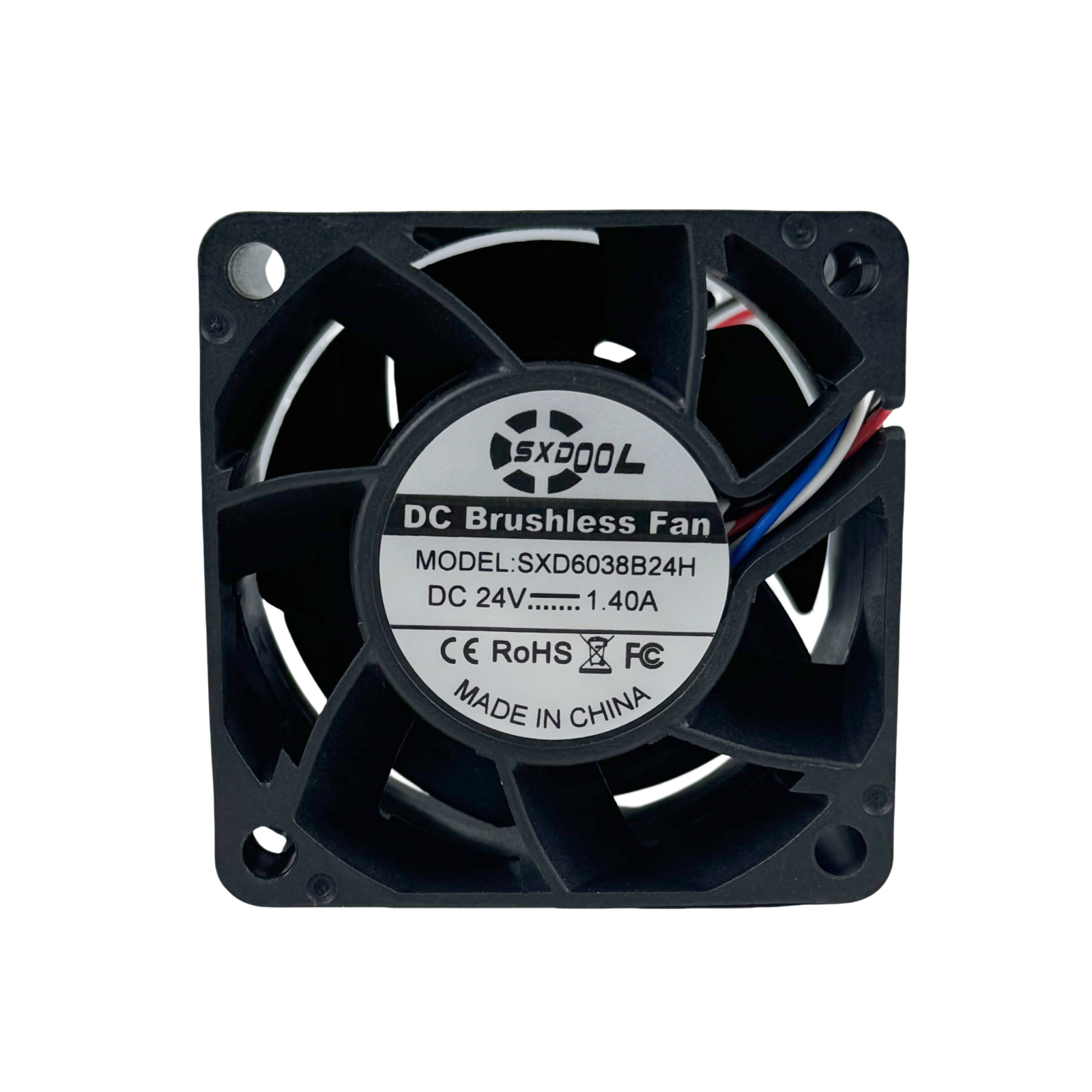
Featured image: Label-view reference photograph from the SXD6038B24H-RDP listing. The photographed label reads SXD6038B24H, DC 24V, 1.40A; it does not show the RDP suffix. Confirm the exact offered configuration and current documents separately. This is a loose sample, not an installed rack-server module or a server qualification result.
Request configuration-matched technical documents through the document center. An equipment manufacturer’s cooling example explains a design question; it does not supply missing SXDOOL product data.
Balance noise, maintenance and thermal margin
Define where the server operates: a staffed office, a laboratory or a separate equipment room can have different acoustic needs. Measure the complete chassis at a stated listener position and operating mode. Include steady load, startup, control transitions and the specified degraded condition; a quiet idle result cannot stand for full-load cooling.
For an OEM design, reduce unnecessary inlet obstruction, bypass and structural vibration before assuming that more speed will solve the problem. Check any damping arrangement against mounting security and the required service method. Do not promise a decibel reduction from a generic speed ratio or transfer a free-standing fan’s noise result to the assembled server.
Define the expected inlet temperature, altitude and contamination exposure, then verify the exact equipment and fan limits. Inspect accessible grilles, installed filters if the chassis uses them, cable clearance and fan-module seating as part of the maintenance plan. A component’s ingress claim would not establish the protection of an open-air server chassis.
Qualify the final populated assembly
Agree limits and measurement points from the exact component and equipment documents. Record the server revision, fan sample identity, hardware population, firmware and thermal policy, inlet conditions and workload. Test the complete assembly rather than extrapolating from one fan on a bench.
| Condition | Evidence to retain | Decision it supports |
|---|---|---|
| Maximum intended processor, memory and expansion configuration | Inlet and component temperatures, workload, throttling status, control command and fan response after stabilization | Whether every critical zone meets its defined limit |
| Supported alternative drive, riser and cable populations | Installed shrouds, blanks, flow direction and any changes in the hottest component | Whether a configuration change invalidates the original airflow result |
| Startup and controller transitions | Supply behavior, control waveform, feedback or alarm response and event-log interpretation | Whether the electrical interface works without disabling fault detection |
| Specified degraded and service conditions | Exact fault definition, controller response, remaining cooling and component temperatures | Whether the required redundancy and service limits are met |
| Acoustic and maintenance conditions | Measurement location, operating mode, tones or vibration, and the agreed intake condition | Whether the design remains acceptable to operators through its intended service interval |
Carry out fault and service testing on a controlled qualification system using an approved procedure. The criteria should state when operation must stop or load must be limited; they should not assume that every failed-fan condition permits continued full-load operation.
Rack server fan questions
Can a high-pressure fan replace an existing server fan module?
Only after the complete assembly and interface are approved for that equipment. Check the carrier, connector, pinout, supply, control, feedback, flow direction and thermal results. For a proprietary server, use the manufacturer’s approved replacement and service path. A shared frame size or larger maximum pressure does not establish interchangeability.
Will extra cabinet fans fix an internal server hot spot?
Cabinet ventilation can address the air supplied around the equipment, but it does not establish airflow through a blocked heat sink or poorly supplied expansion zone. Measure conditions at the server inlet and examine its internal airflow path before deciding which part of the cooling system needs to change.
Does an N+1 claim mean I can remove one fan module?
Check the exact equipment definition. Redundancy may refer to a rotor rather than a complete removable module, and service may have separate limits. Use the actual server’s population and service rules; agree a separate fault test for a new OEM design.
Is SXD6038B24H-RDP already qualified for my rack server?
No server-specific qualification is established by this guide. It is a named starting point for requesting current model-matched evidence. Selection remains conditional on the released configuration, mounting, controller, operating-point, thermal, acoustic and service requirements of your chassis.
Send the chassis requirements for a fan review
Provide a chassis layout and mounting drawing; processor, memory, drive and expansion population; heat loads and component limits; measured or estimated airflow resistance; inlet temperature and altitude; acoustic target; supply and startup budget; controller pinout, control and fault requirements; and the intended redundancy and service procedure. State whether this is a new OEM design or a replacement request, and include the full original fan-module part number for a replacement.
For the SXD6038B24H-RDP reference, request the current released configuration and identify unresolved requirements before ordering evaluation samples. Production selection needs the matching documents and an accepted equipment test result.
Request a rack server fan review
Related resources: industrial cooling applications · DC, AC and EC fan selection · fan-interface questions.
Technical sources checked October 21, 2026. Equipment examples apply to their named products and revisions; they do not approve an SXDOOL fan for those systems.