Blog
60mm PWM Fan Integration: Wiring, Alarm and Startup Checks

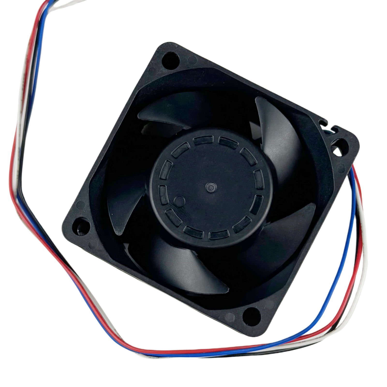
A four-wire cooling fan does not necessarily provide an RPM feedback signal. For an OEM controller, the important distinction is between the input that commands fan speed and the output that reports fan status. The SXDOOL SXD6038B24H-RDP is a useful model-specific example: this 60 x 60 x 38 mm, 24 VDC configuration combines PWM control with an RDB locked-rotor alarm. FG tachometer output is not selected.
This guide is for engineers evaluating a compact cooling module with a controllable fan and a separate fault indication. It focuses on the interface and sample-approval decisions that should be resolved before ordering, rather than treating every 6038 fan as interchangeable.
Start with the controller’s actual information requirement
Write down what the equipment needs to know. Is a running-or-fault indication sufficient, or must the controller display and regulate actual RPM? These are different requirements. PWM is a command input; it is not a measured-speed output. An RDB alarm does not supply the FG pulse train needed for tachometer-based RPM measurement.
For SXD6038B24H-RDP, a controller that expects FG feedback needs a separately reviewed interface or fan configuration. Do not reinterpret the alarm conductor as a tachometer signal to make a connector appear compatible. General fan sensor documentation also distinguishes pulse sensing from locked-rotor sensing; another manufacturer’s example circuit is not a wiring specification for this SXDOOL model.
Approve a pinout and signal sheet together
The documented RDP harness has four unterminated, 300 mm leads. It is not a pre-qualified plug-in interface to an arbitrary controller. Before selecting a connector, ask the fan and controller owners to agree on these items:
- Supply and return identification, connector cavity numbering and the mating-view orientation.
- The separate PWM input and RDB output connections.
- PWM logic levels, drive requirements and frequency.
- Alarm output circuit, permitted electrical loading, normal/fault levels and reporting delay.
- The controller response during power-up, commanded stop and a detected fault.
The model’s documented PWM frequency range is 1-50 kHz, with 25 kHz preferred. Frequency agreement alone does not establish electrical compatibility. Do not copy a pull-up voltage, resistor or fault polarity from a different fan’s drawing.
Keep startup current separate from running current
The confirmed values for this configuration are 1.1 A rated running current and 1.40 A startup current at its 24 VDC rating. A supply review based only on the running figure misses the startup requirement. Conversely, the startup figure is not evidence of a guaranteed worst-case transient peak, its duration, or locked-rotor current.
During a controlled sample evaluation, record voltage at the fan connection and the startup current waveform. Review cable voltage drop and supply current limiting with the equipment engineer. If several fans start together, assess that sequence rather than assuming the behavior of one sample proves the complete assembly.
Distinguish commanded stop from a fault
The reviewed specification states that this model stops at 0% PWM duty. The equipment therefore needs a defined policy for a fan that has intentionally been told to stop. Agree which status the controller should report, and when fault monitoring becomes active again after a start command.
A practical review records the command, observed rotation and alarm state through power-up, normal running and commanded stop. Resolve the model-specific alarm truth table before approving the software. Any abnormal-condition testing belongs in an engineering-controlled procedure; do not block the rotor by hand or change live wiring to create a fault.
Qualify the cooling path as well as the electronics
A correct signal connection does not prove that the installed equipment is adequately cooled. Check the available 38 mm fan depth, inlet and outlet clearance, mounting drawing and cable routing. Use the matching pressure-airflow curve to review the enclosure’s restriction, then evaluate component temperatures and acoustic performance in the actual assembly.
A compact power-electronics enclosure is an example of where this review may be useful, not a claim that the fan has already been qualified for a particular power supply, charger or customer system.
Questions to resolve before sample approval
Can an existing four-pin connector establish compatibility?
No. Compare the connector orientation, contact assignment and signal definitions. An interface expecting an RPM pulse output is not equivalent to an alarm interface merely because both use four conductors.
Can the controller infer exact RPM from the PWM duty setting?
Do not use the command as an RPM measurement. This configuration has no selected FG output. Specify an actual-speed feedback requirement explicitly if the equipment needs it.
What belongs in the approval record?
Keep the complete model suffix, sample identification, wiring-drawing revision, controller interface revision, startup observations, command/status behavior and equipment-level thermal results together. Record unresolved items instead of marking them passed.
Send SXDOOL a controller-integration RFQ
Include SXD6038B24H-RDP, your supply range, PWM interface, required alarm behavior, mounting constraints, operating environment and quantity in your sample or quotation request. Attach the relevant connector or controller interface drawing, and identify whether alarm indication or measured RPM is required. Engineering inquiries can also be sent to david@sxdool.com.