Blog
Cooling Fans for Laboratory Diagnostic Analyzer Electronics

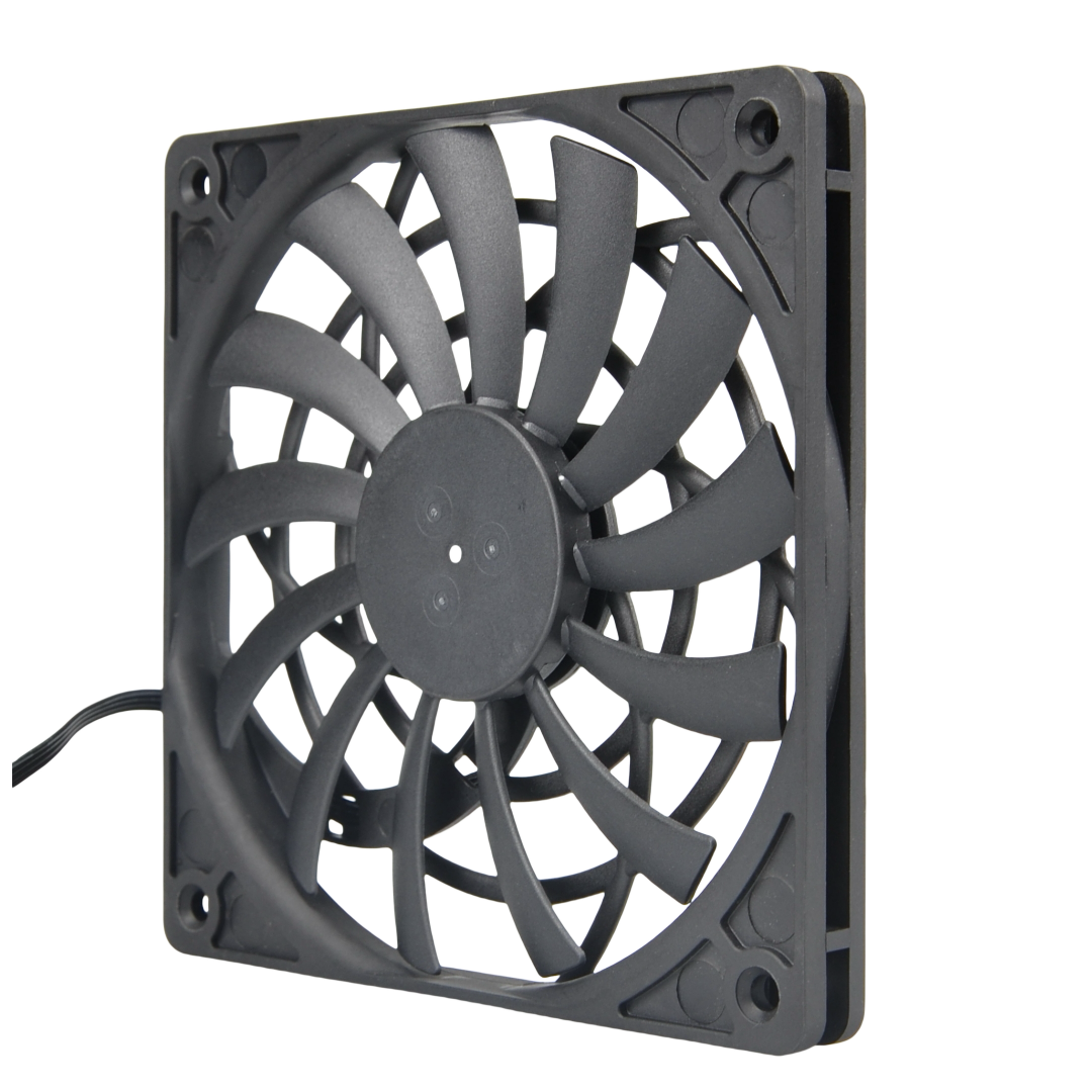
For a laboratory diagnostic analyzer, evaluate its electronics cabinet airflow separately from the temperature control of reagents, cuvettes and reaction zones. A slim fan can be considered where depth is restricted, but its installed airflow through the actual filter and enclosure must be measured before approval. This guide proposes an SXDOOL sample for engineering review; it does not claim a qualified replacement in any clinical instrument.
Map the analyzer’s separate thermal zones
Identify the heat sources before choosing a fan: power-supply losses, controller and computing boards, motor drives, and any optical electronics. Mark the cabinet inlet, filter, fan position, exhaust, baffles and service access on the instrument drawing. Then identify sealed or actively controlled reagent, cuvette and reaction zones. Moving air through the electronics cabinet is not the same as regulating those process temperatures.
As a model-specific example of separated air paths, Siemens Healthineers’ Dimension EXL filter maintenance material identifies cabinet, cuvette-ring, power-supply and thermal-chamber filters in different positions. Its maintenance interval and procedures apply to those Siemens systems only; use the actual analyzer’s operator manual for service and safety. This example does not imply that an SXDOOL fan is installed or approved there.
Check the installed air path, not only free-air fan flow
A clean filter, a loaded filter, a narrow grille and the assembled cable route can create different pressure losses. Measure or calculate the required airflow at the electronics hot spots, then compare it with the pressure–airflow curve of the exact fan configuration and the measured system resistance. Record the worst permitted inlet condition and filter-service threshold. A spinning fan or a nominal free-air value cannot show that the cabinet receives enough cooling.
| Equipment constraint | What to verify |
|---|---|
| Shallow electronics bay | Allow for the fan frame, guard, fasteners, cable bend, intake gap and exhaust clearance in the complete assembly. |
| Filter and restricted vents | Compare clean and service-threshold pressure losses with the exact fan variant’s curve at the needed airflow. |
| Optical or measurement assembly nearby | Test vibration coupling and acoustic noise in the assembled analyzer at its defined operating modes. |
| Fan monitoring or fault response | Confirm the exact wiring, speed or airflow sensing, alarm logic and safe-state behavior specified by the instrument designer. |
Why evaluate the SXDOOL 12012 slim fan family?
The SXDOOL 12012 slim DC axial fan family lists a 120 × 120 × 12 mm frame. The pictured SXD12012S12M is a 12 V sample. The family also lists separate 5 V and 24 V configurations; these are not one universal-input unit. Its low profile makes it worth reviewing for a shallow electronics bay that can accommodate a 120 mm frame and an axial air path.
Frame size and sample voltage do not establish installed airflow, noise, vibration, medical-device compliance or analyzer compatibility. Before sample approval, request the controlled drawing, exact-version pressure–airflow curve, acoustic test conditions, current and startup limits, connector and signal definition, material declaration and relevant quality documents. If the resistance or mounting envelope rules out this slim variant, compare a different fan and duct arrangement rather than assuming interchangeability.
Featured image: Real SXDOOL 12012 family sample photograph, showing the impeller side and frame. The visible face has no readable voltage label; confirm the ordered sample against its own label and drawing. This is a product reference, not an analyzer installation or a tested fit.
When is the slim fan a useful analyzer candidate?
Continue evaluating the SXD12012S12M sample when the electronics bay can accommodate its complete assembly and the exact fan’s curve supports the required airflow through the filter and vents. Limited depth is a reason to investigate this family; it does not establish that the slim sample can overcome the actual enclosure resistance.
- Define the compartment being cooled. Identify electronics hot spots, temperature limits, inlet conditions and duty cycle. Mark the barriers separating electronics ventilation from reagent, reaction and other controlled zones.
- Match the exact sample documentation. Use the ordered SXD12012S12M version’s drawing, supply and startup limits, connector and any specified control or fault interface. Do not substitute data from another fan family or voltage configuration.
- Test with the assembly complete. Measure the installed operating point and electronics temperatures with the specified covers, filter, guards and cable route. Include the instrument maker’s defined filter-service condition and confirm service access.
- Check nearby measurement functions separately. Assess mounting vibration and acoustic behavior in the instrument’s required modes, alongside the instrument maker’s own measurement-performance and fault-response checks. Do not bypass guards, covers or interlocks.
Accept or revise the design: retain the sample only when the electronics-cooling limits and the instrument’s other applicable checks pass. If filter resistance prevents the required airflow, compare a different fan or duct arrangement. If ventilation disturbs a controlled process zone or a measurement assembly, review the air-path separation and mounting before approving a fan change. Record the sample identity, drawing revision, filter condition, instrument mode and measured result together.
This is an electronics-cooling selection path. It does not claim improved assay accuracy, reagent stability, sterile airflow or regulatory approval. Any such requirements must be demonstrated under the instrument maker’s own qualification plan. If the task is a controlled reaction or reagent chamber rather than electronics ventilation, specify that as a separate thermal-control problem.
Laboratory analyzer cooling questions
Does higher fan airflow improve analyzer accuracy?
Not by itself. Electronics temperature, vibration, reagent conditions and analytical performance have separate acceptance tests. Validate the assembled instrument under its defined conditions; a fan change alone does not prove diagnostic accuracy.
Can a cabinet fan control reagent or reaction temperature?
Do not assume it can. Cabinet ventilation removes electronics heat, while reagent and reaction zones may be isolated or actively temperature-controlled. Follow the exact instrument design and verify each zone against its own limits.
What should an OEM fan inquiry include?
Send the electronics-bay drawing, heat loads, inlet temperature, filter and duct resistance, supply and wiring, available depth, target airflow, noise and vibration limits, fault-handling requirement and the compliance evidence needed for the project. State whether the request concerns cabinet ventilation or a controlled process zone.
Request a configuration-specific evaluation
Send the instrument-compartment and filter/duct drawings with the operating conditions above. Identify the exact SXD12012S12M 12 V sample or request a different voltage configuration. The RFQ starts a technical review; it does not establish installed compatibility.
Discuss the analyzer cooling requirementExplore more industrial cooling applications
Public evidence check: 21 October 2026. The current public page does not add a model-specific pressure–airflow curve or drawing; request the exact SXD12012S12M configuration documents before approval.