Blog
Advanced System Curve and Fan Selection

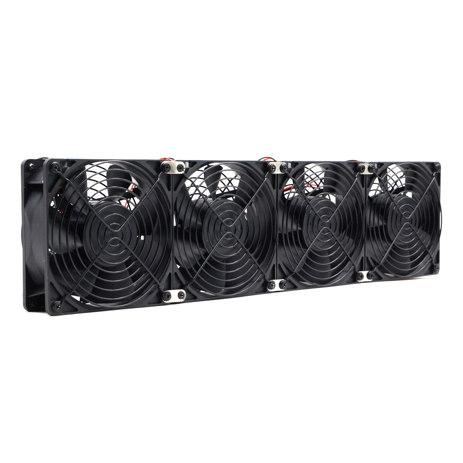
Advanced analysis scope
For turbulent enclosure flow, a first approximation often uses pressure loss proportional to airflow squared. Establish test points, fit the system curve, intersect it with the candidate fan curve and carry uncertainty for filters, tolerances and ambient density. Confirm the result in hardware.
The Fundamentals of Thermal Management
In the world of high-performance electronics, thermal management is often the silent bottleneck that determines the reliability and longevity of a system. When engineers sit down to design a cooling solution, the most common reflex is to look for a fan with the highest CFM (Cubic Feet per Minute) rating that fits within the physical dimensions of the chassis. However, selecting a fan based solely on its “free air” performance is a fundamental error that leads to under-cooled systems, excessive noise, and premature component failure. To select a fan professionally, one must first understand and calculate System Impedance.
System impedance, also known as airflow resistance, is the measure of the pressure drop that occurs as air moves through a system. Every component inside an enclosure—PCB boards, heat sinks, cables, connectors, and even the intake and exhaust vents—acts as an obstacle to airflow. As air strikes these objects and changes direction, it loses energy, resulting in a decrease in pressure. Matching the fan’s performance curve to this system resistance curve is the only way to ensure the desired airflow is actually achieved under real-world operating conditions.
The Physics of Airflow Resistance: Understanding the K-Factor
Airflow resistance follows the principles of fluid dynamics. In most electronic enclosures, the relationship between the pressure drop (ΔP) and the airflow rate (Q) can be simplified into a quadratic equation:
ΔP = K · Qn
Where:
- ΔP is the static pressure drop across the system.
- Q is the volumetric airflow rate.
- K is the system impedance constant (the K-factor).
- n is a constant that typically ranges from 1 to 2. For most turbulent airflow in electronic systems, n is approximately 2.
The K-factor is unique to every unique mechanical design. A system with a high K-factor is “restrictive,” meaning it requires a significant amount of pressure to push a small volume of air through it. Conversely, a system with a low K-factor is “open,” allowing air to flow more freely. The K-factor is determined by the density of the internal components, the geometry of the air paths, and the surface roughness of the materials used.
Fan Curves vs. System Resistance Curves
To visualize how a fan will perform, we use a P-Q Diagram. A fan’s performance is represented by a downward-sloping curve, starting at the maximum static pressure (zero airflow) and ending at the maximum airflow (zero static pressure). The system impedance is represented by an upward-sloping parabolic curve starting at the origin (0,0).
The point where these two curves intersect is the Operating Point. This point represents the actual airflow and static pressure that will exist when the fan is installed in that specific system. If the system impedance is too high, the operating point will shift to the left, significantly reducing the actual airflow. This is why a 100 CFM fan might only deliver 30 CFM once it’s mounted behind a dense filter and a crowded PCB rack.
The SXDOOL 12038 Series: A Case Study in High Impedance Handling
For systems with high impedance—such as server racks, telecom power supplies, and industrial battery storage units—a standard 12025 (120x120x25mm) fan often lacks the static pressure needed to overcome the resistance. This is where the SXDOOL 12038 series excels. By increasing the depth of the fan to 38mm, we allow for more aggressive blade angles and a more powerful motor, resulting in a significantly “stiffer” P-Q curve.
In our technical audits, we frequently see designs where a 12025 fan is running at its stall region because the system impedance was underestimated. By switching to the 12038 series, engineers can achieve the same airflow at a lower RPM, which not only reduces noise but also extends the bearing life of the fan. The additional 13mm of depth provides the mechanical leverage required to maintain airflow against the back-pressure generated by modern high-density component layouts.
Optimizing Your Enclosure for Maximum Thermal Performance
While selecting a powerful fan is one part of the equation, professional engineers also work to minimize the system impedance. Here are several strategies to optimize your enclosure:
1. Aligning the Airflow Path
Air is like electricity; it takes the path of least resistance. If there is a large gap between the fan and the components that need cooling, the air will bypass the “hot spots” and flow through the empty space. Using baffles and ducting to force air across critical heat sinks can reduce the total airflow required, thereby lowering the pressure requirement.
2. Reducing Intake and Exhaust Restriction
Intake grilles and exhaust vents are often the biggest contributors to the K-factor. A common mistake is using a decorative grille with a low “open area” percentage. For optimal performance, the open area of a vent should be at least 60-75% of the total surface area. Hexagonal patterns generally offer a better balance of structural integrity and airflow efficiency compared to simple circular holes.
3. Managing Cable Bulk
In dense industrial cabinets, cable management is a thermal issue as much as an aesthetic one. Bunched cables acting as “air dams” can create localized high-impedance zones. Using cable trays and routing wires along the walls of the enclosure helps maintain a laminar flow path.
Calculating System Impedance: Practical Steps
How do you find your K-factor? There are three primary methods:
- Computational Fluid Dynamics (CFD): Software like Ansys Icepak or SolidWorks Flow Simulation can predict the system resistance curve with high accuracy before a physical prototype exists.
- Flow Bench Testing: A physical prototype is connected to a calibrated air chamber (flow bench). By measuring the pressure drop at various airflow rates, the K-factor can be empirically derived.
- Approximation by Analogy: For simpler designs, engineers can use lookup tables for common components (e.g., “Standard ATX Chassis Impedance”) to estimate the resistance.
Once you have the system resistance curve, you can overlay it on the P-Q curves provided in the SXDOOL technical datasheets. If the operating point falls in the “stall region” of the fan curve (the dip usually found in axial fans), you must either find a way to reduce system impedance or switch to a fan with a different blade design, such as a blower or a contra-rotating fan array.
The Role of Variable Speed Control (PWM)
System impedance isn’t static. As filters become clogged with dust, the K-factor increases. As environmental temperatures rise, the air density changes. Implementing PWM (Pulse Width Modulation) control allows the system to respond to these changes. By monitoring the temperature of critical components, the fan speed can be increased to overcome the added resistance of a dirty filter, ensuring the system remains within safe thermal margins throughout its service life.
Conclusion: Engineering Truth in Fan Selection
Professional fan selection is an engineering discipline, not a guessing game. By calculating system impedance and understanding the K-factor, you move beyond “oversizing” fans and into the realm of precision thermal management. At SXDOOL, we don’t just provide fans; we provide the technical audit and the P-Q performance data necessary to build world-class industrial systems. Whether you are cooling a 5G base station or a high-power EV charging pile, the first step is always the same: know your impedance.
For detailed K-factor calculations or to request a flow bench test for your prototype, contact the SXDOOL Technical Engineering Team today.
Deep Dive: The Mathematics of Turbulence
In our initial equation ΔP = K · Qn, we noted that n is typically 2. This is because most industrial cooling applications operate in the turbulent flow regime (high Reynolds numbers). When air flows through a vent or around a square component, it separates from the surface, creating eddies and vortices. These vortices are energy sinks. The pressure required to sustain this turbulent flow increases with the square of the velocity. If your system is extremely small and air speeds are very low, you might enter the laminar regime where n=1, but this is rare in forced-convection cooling of power electronics.
The Impact of Air Density
It is also crucial to remember that P-Q curves are typically measured at Standard Air Density (1.2 kg/m³). If your system is operating at high altitudes (e.g., a telecommunications tower in the mountains) or in extreme desert heat, the air density will be lower. Lower air density means the fan will generate less static pressure for the same RPM. To maintain the same cooling effect, you must compensate by either increasing the fan speed or selecting a fan with a more aggressive P-Q curve. At SXDOOL, we provide altitude compensation tables for our 12038 and 17251 series fans to help engineers navigate these challenges.
Advanced Mitigation: Fan Arrays and Redundancy
When system impedance is exceptionally high, a single fan may not be sufficient regardless of its size. In these cases, engineers employ fan arrays. Placing fans in parallel increases the total airflow (useful for low-impedance, wide systems), while placing fans in series (stacking them) increases the total static pressure (useful for high-impedance, deep systems). SXDOOL’s modular fan frames allow for easy configuration of N+1 redundant arrays, ensuring that even if one fan fails, the remaining units can ramp up to maintain the operating point above the critical threshold.
The Hidden Cost of Impedance: Noise
Finally, we must address the acoustic impact. A fan working against high impedance is a loud fan. When a fan operates near its stall point, the air turbulence at the blade tips increases significantly, creating a high-pitched “whooshing” or “whining” sound. By reducing system impedance through better mechanical design, you allow the fan to operate in its high-efficiency, low-noise region. This is particularly important for medical imaging equipment and office-based server units where acoustic comfort is a primary requirement.
A Commitment to Precision
At SXDOOL, our manufacturing process in Dongguan is centered around consistency. We use precision CNC winding and automated assembly to ensure that every fan we ship matches the P-Q curve in our catalog. This reliability allows you to design your system impedance calculations with confidence, knowing that the “Operating Point” you calculate on paper will be the one you see in the lab. Engineering excellence begins with data, and it ends with a perfectly cooled system.
Related engineering resource
Continue with System Impedance Basics for Fan Selection for the adjacent decision stage. The two pages address different search intents and should be used together.
Project-specific FAQ
How can a system curve be estimated from test data?
Measure static pressure at several controlled airflow points and fit an appropriate loss relationship. Use consistent density and measurement locations, then document uncertainty.
Do two identical fans in parallel deliver twice the airflow?
Not generally. Their combined curve interacts with the same system resistance, and inlet or outlet coupling can reduce the ideal gain. Validate the assembled arrangement.
How should filter loading be represented?
Create clean and loaded-filter system curves or add the specified pressure drop at the relevant flow. Select with enough margin for the planned maintenance interval.
Project review: Send the operating conditions, target airflow, static pressure, voltage, size, cable and connector requirements to david@sxdool.com for a model-specific review and factory quotation.