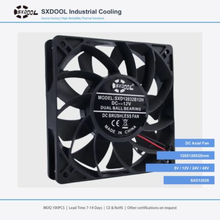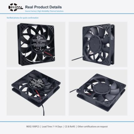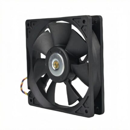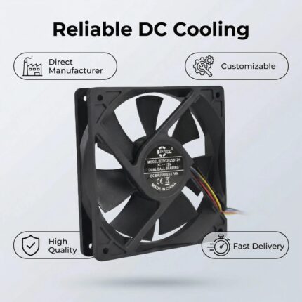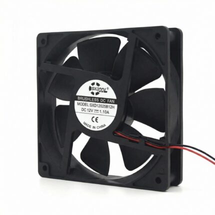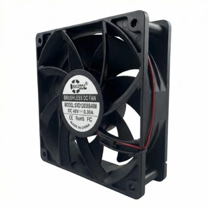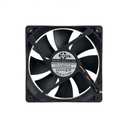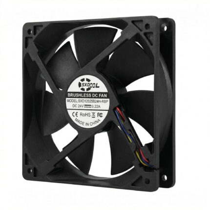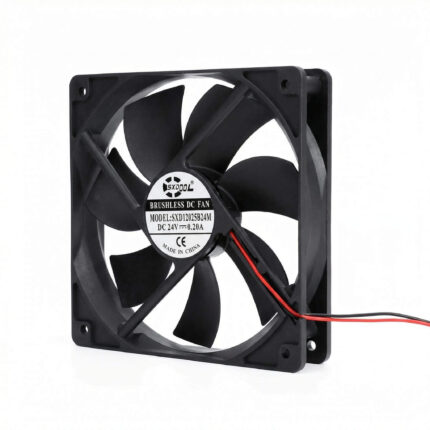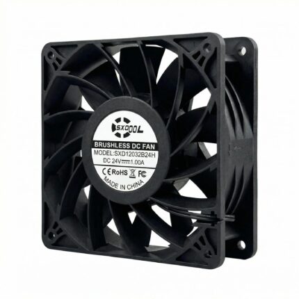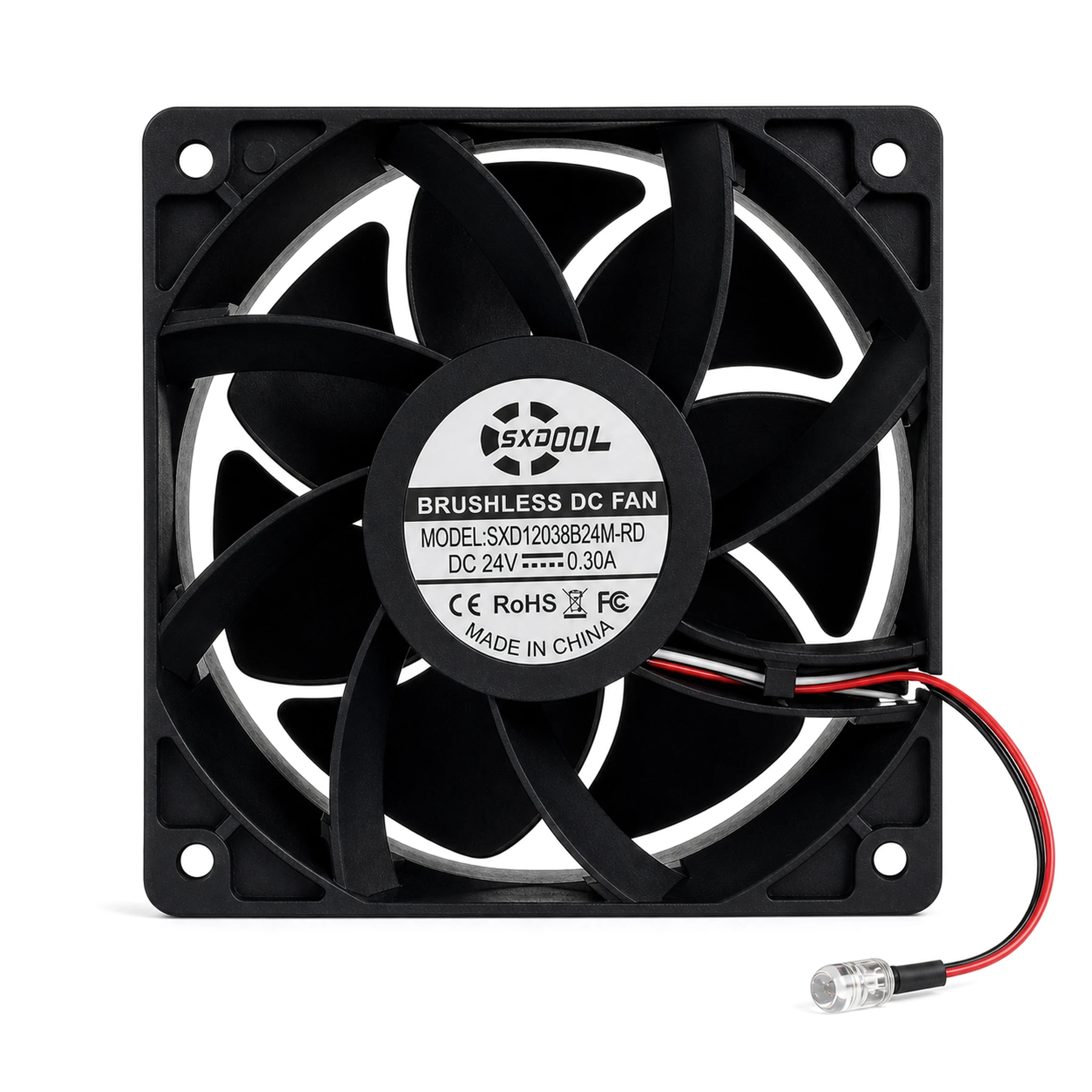
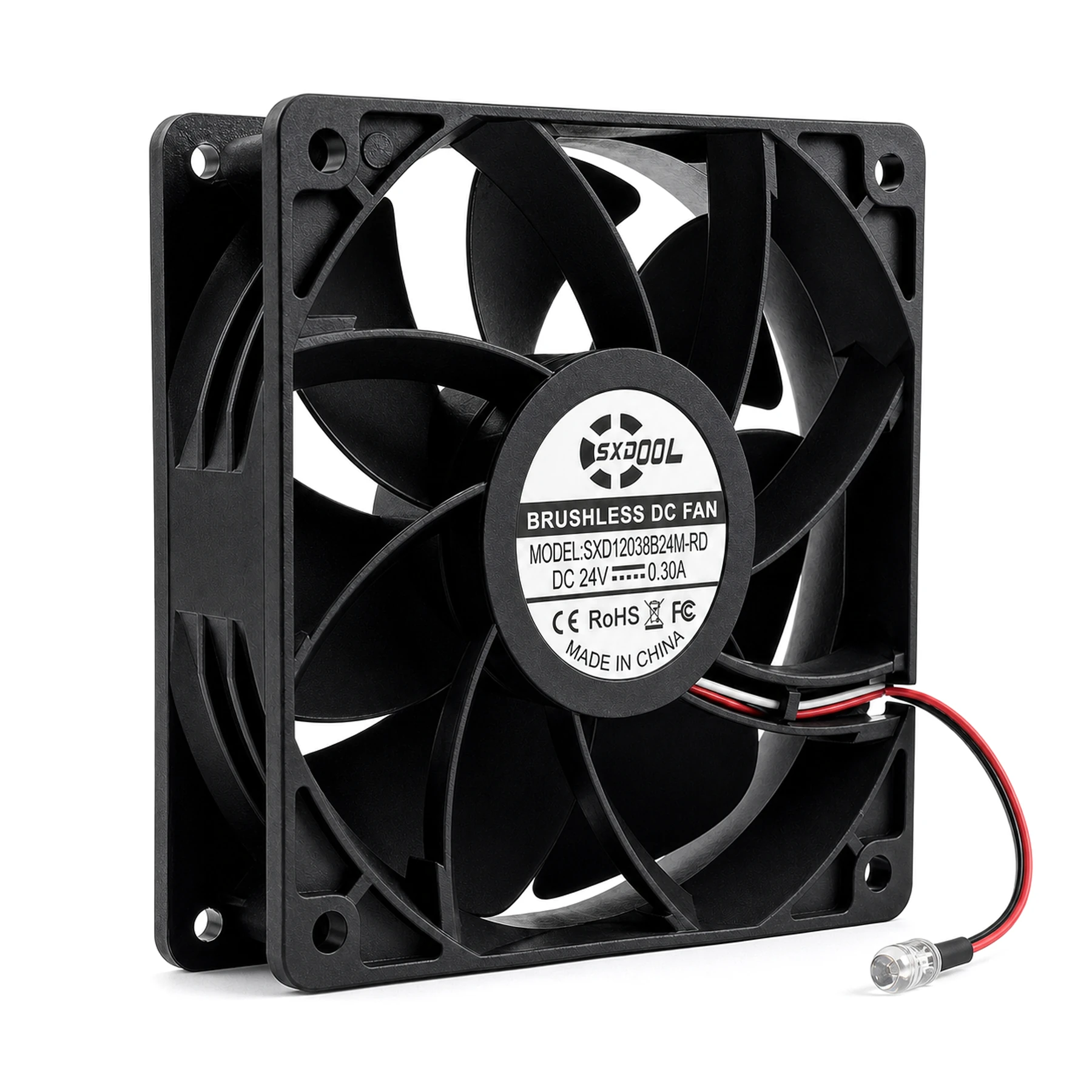
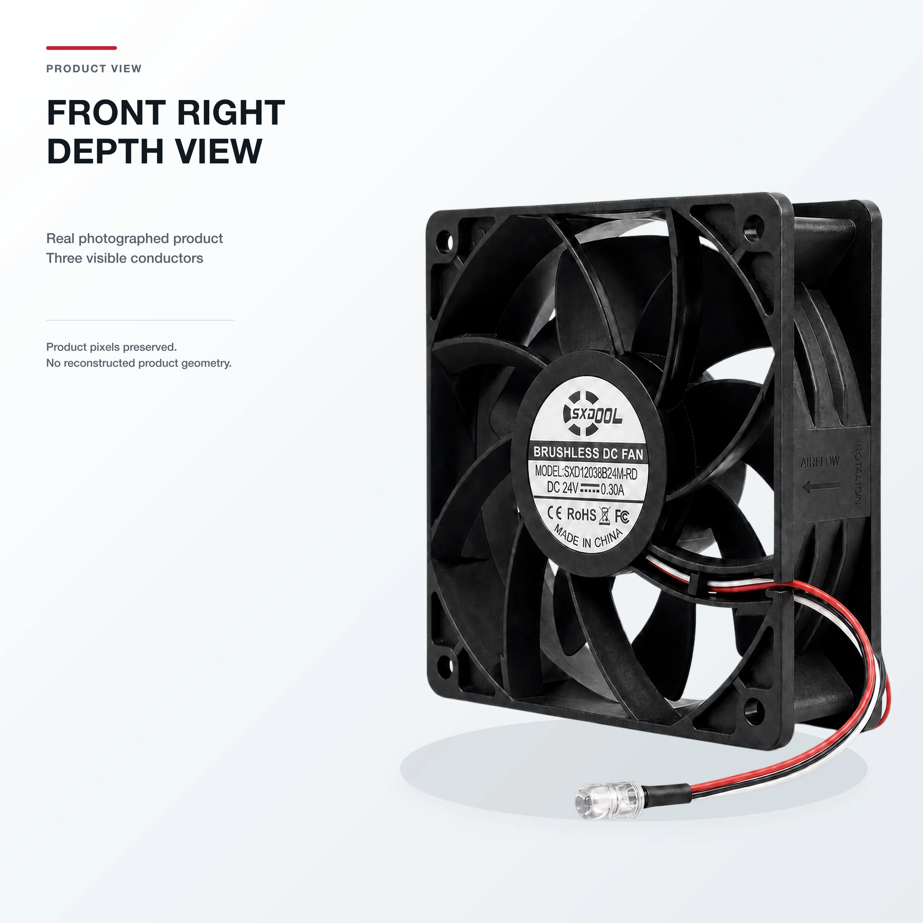
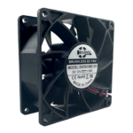
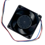
120x120x38mm 24V three-wire brushless DC axial fan with an RD stop-detection output and external alarm indicator. Designed for industrial cooling and OEM projects where a stopped-fan condition needs a visible or controller-level indication. Final pinout, alarm circuit, electrical interface, and performance data must follow the approved production specification.
12038 INDUSTRIAL DC AXIAL FAN · 24V · RD STOP DETECTION
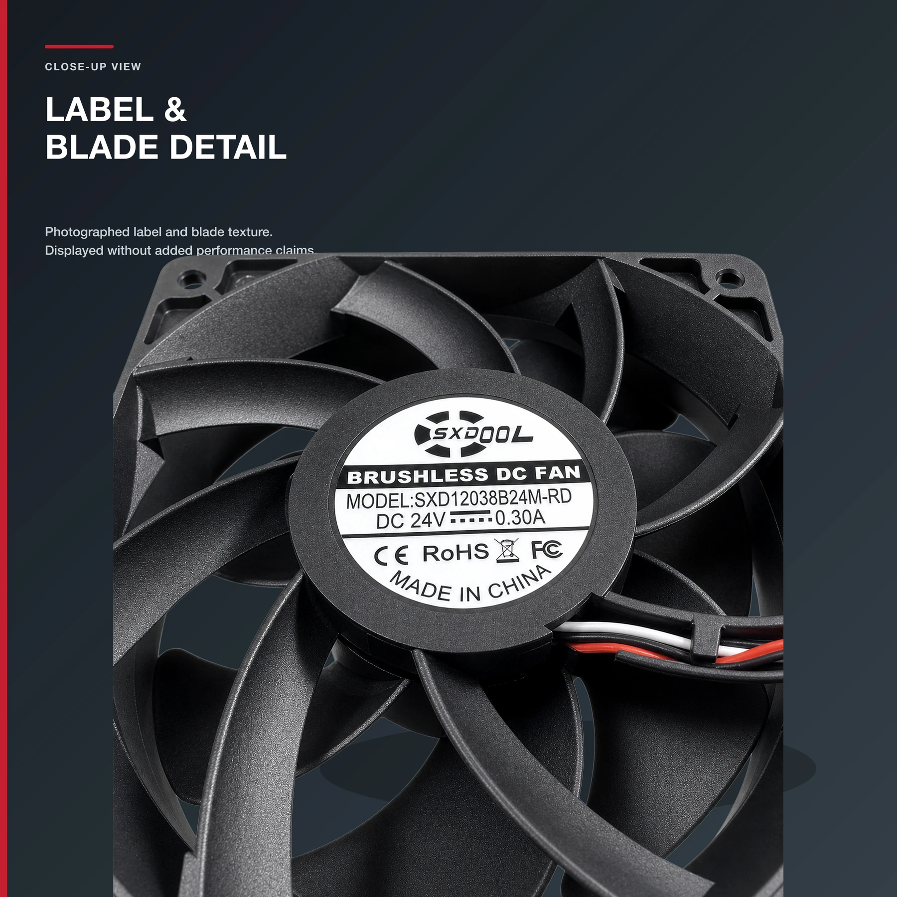
SXDOOL SXD12038B24M-RD 120x120x38mm 24V DC Axial Fan with RD Stop Detection
A three-wire 24V brushless DC axial fan designed for engineering projects that need a visible or controller-level indication of a stopped-fan condition.
Equipped with an RD stop-detection output and an external alarm indicator to help identify a fan-stop condition when used with the confirmed wiring circuit.
What is the SXD12038B24M-RD?
The SXD12038B24M-RD is a 120x120x38mm, 24V, three-wire DC axial fan configuration with an RD stop-detection output and an external alarm indicator. It is intended for OEM cooling projects where maintenance teams or equipment controllers need a clearer indication that a fan has stopped. Final electrical interface, pinout, duty point, and installation details must be confirmed for the approved production specification.
SXD12038B24M-RD engineering specification status
This table separates confirmed public facts from values that must follow the approved production specification. It prevents RD stop detection from being confused with FG speed feedback or PWM speed control.
| Model | SXD12038B24M-RD |
|---|---|
| Dimensions | 120x120x38mm frame class |
| Rated input platform | 24V DC |
| Motor / airflow type | Brushless DC axial fan |
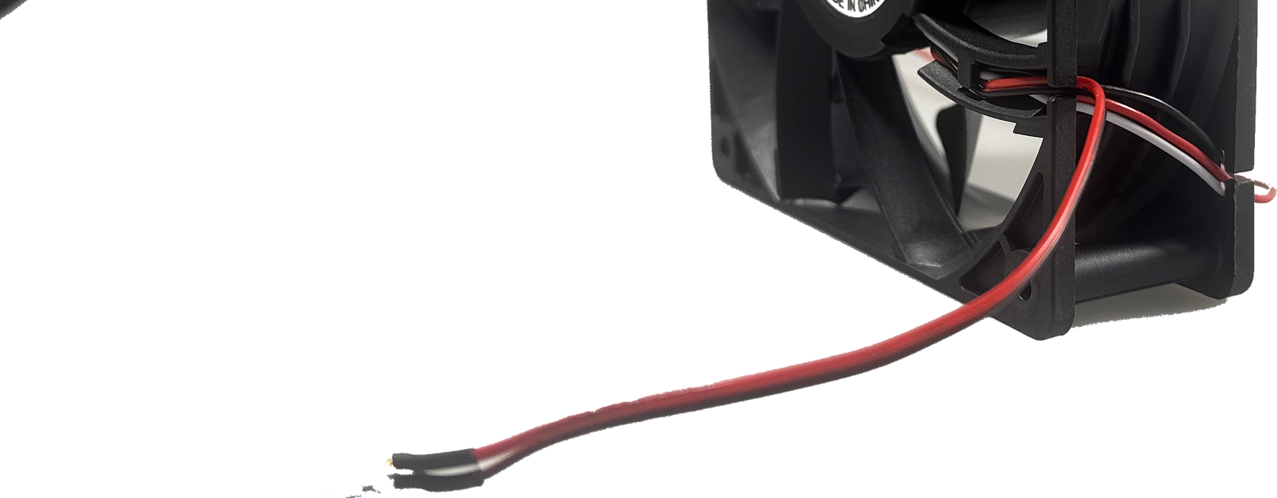
| Visible wiring | Three leads; do not assign pin functions by wire colour |
| Signal function | RD stop-detection output. No FG tachometer or PWM control claim is made for this SKU. |
| External indicator | Supports a visible stopped-fan indication when used with the confirmed wiring and interface circuit |
| Airflow / static pressure | Confirm the required duty point against the approved sample and actual equipment resistance. |
| Speed / noise / current / power | Not asserted as universal values on this page; confirm the approved production specification. |
| Bearing / material / environmental limits | Confirm the selected production configuration and project qualification requirements before sample approval. |
| Applications | Monitored cooling for control cabinets, power equipment, automation systems, chargers, and communications equipment, subject to thermal and interface validation. |
| Manufacturer and quality review | SENSDA ELECTRONICS LIMITED / SXDOOL. ISO 9001:2015 quality-management documentation, OEM/ODM cable and connector requirements, Dynamic Balancing, and 100% End-of-Line Testing can be reviewed against the approved production control plan. |
For RD interface review, sample qualification, or an OEM quotation, contact david@sxdool.com.
VISIBLE MAINTENANCE CUE
RD output plus an external alarm indicator
The external indicator gives technicians a practical visual cue when the confirmed circuit recognizes a stopped-fan condition. The final alarm state, response timing, power source, and interface components must follow the approved wiring specification.
- Supports stopped-fan condition indication.
- Useful for cabinet, power, automation, and equipment-maintenance workflows.
- Can be reviewed with custom cable, connector, terminal, and indicator-interface requirements.
RD, FG, and PWM are not interchangeable
Stop or lock-condition detection output. This is the public function described for this product.
Pulse/frequency output generally used for speed feedback. No FG claim is made for this product.
External speed-control input. No PWM claim is made for this product.
ENGINEERING SELECTION
Designed for industrial airflow projects
This 12038 platform can be evaluated for control cabinets, power equipment, automation systems, chargers, communications equipment, and other forced-air cooling assemblies. Suitability depends on the actual heat load, pressure drop, mounting geometry, environment, and required fault-response design.
Before sample approval: confirm the final model name, current, pinout, RD electrical logic, alarm circuit, airflow, static pressure, speed, noise, bearing, cable, connector, and environmental limits.
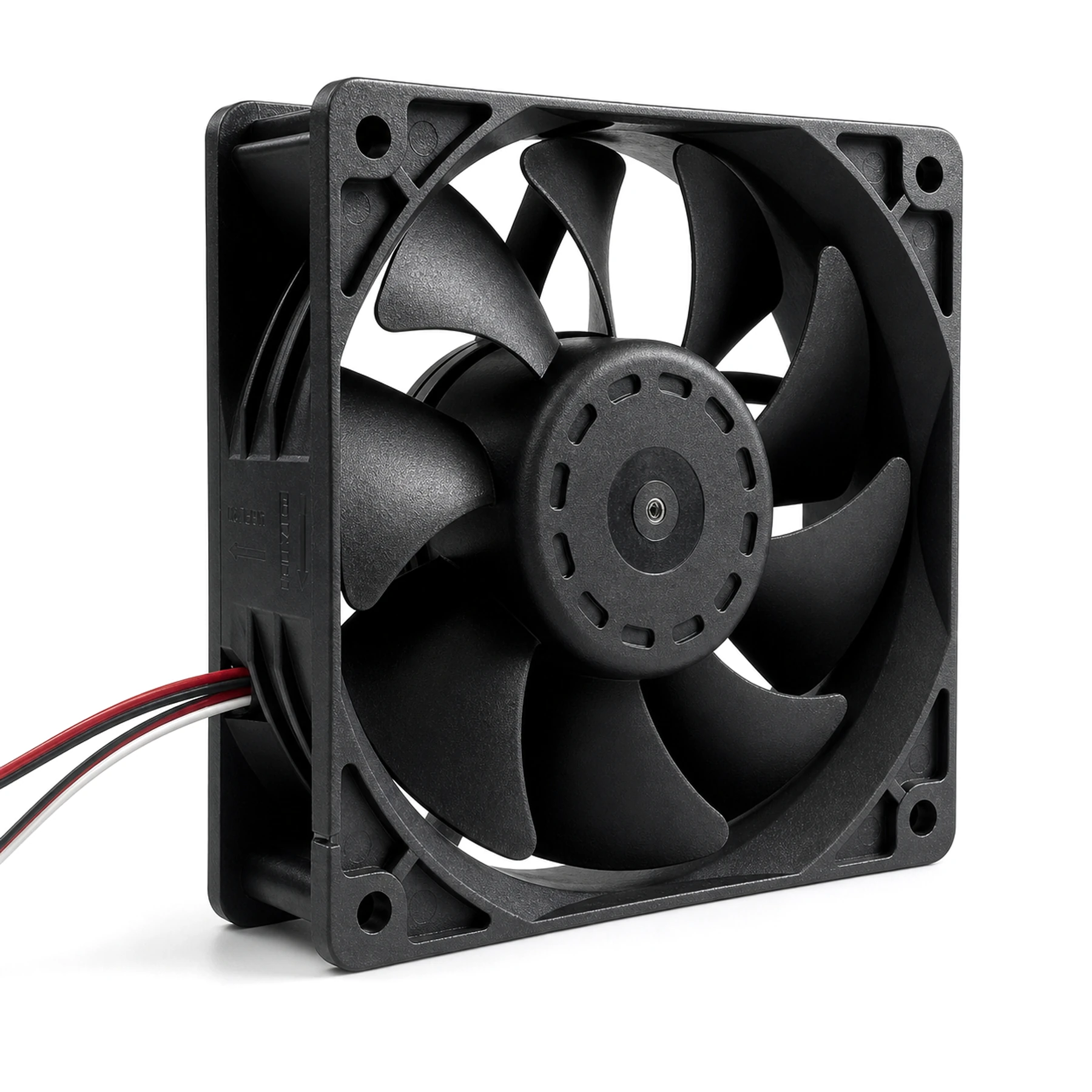
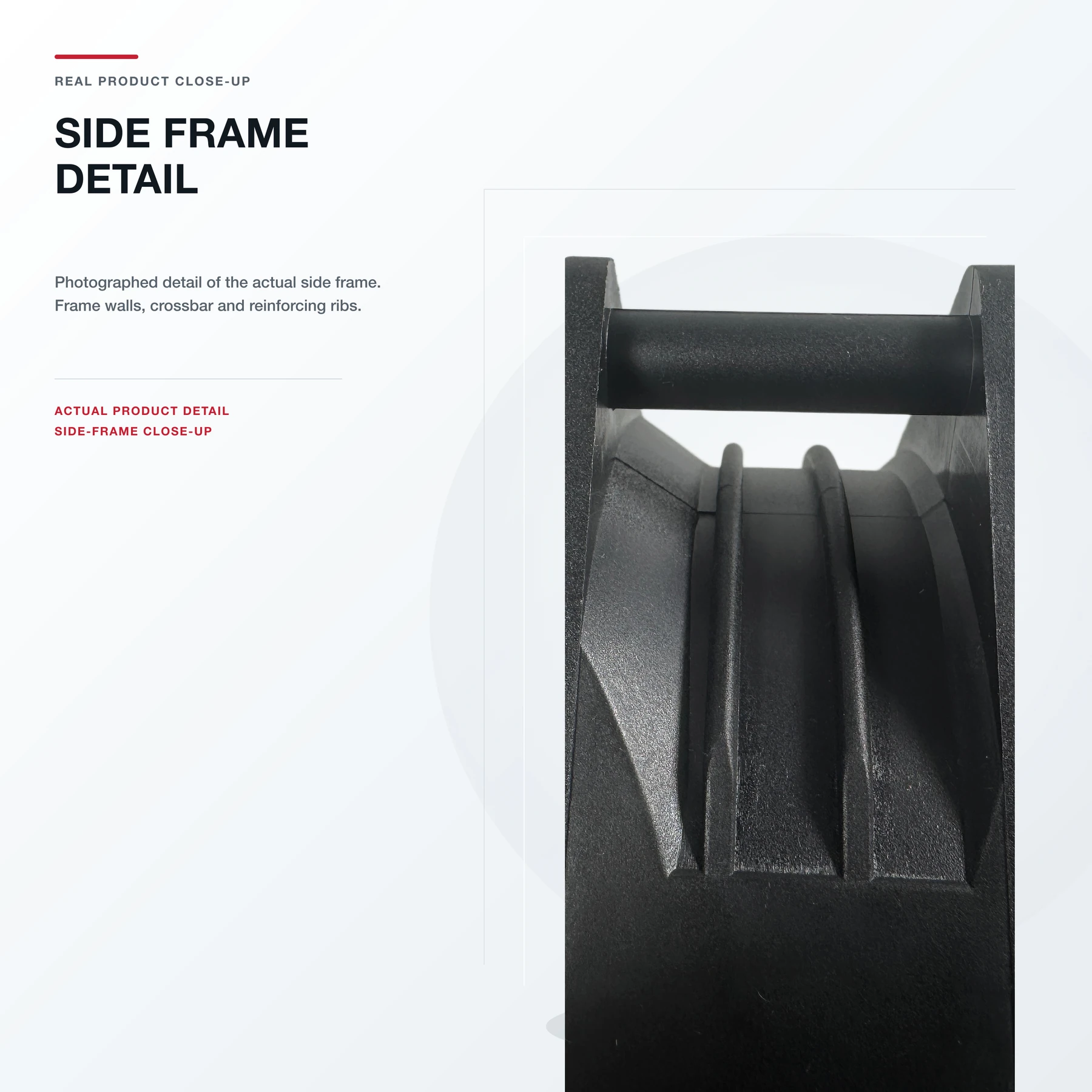
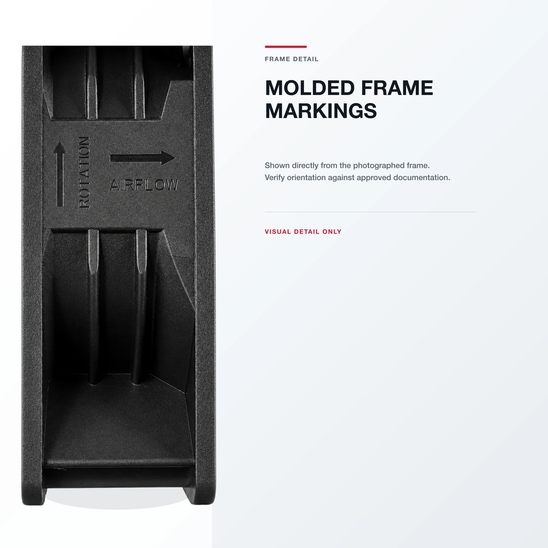
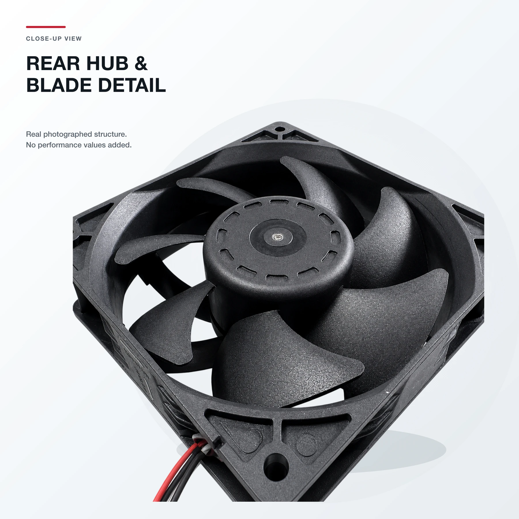
Real-product structure and details
ENGINEERING FAQ
Questions buyers should confirm before an RFQ
What does the RD output do on this fan?
The RD output is intended to support fan-stop detection. When used with the confirmed external circuit, it can help a controller or indicator identify a stopped-fan condition.
Is RD the same as an FG tachometer signal?
No. RD and FG are different functions. RD is used for stop or lock detection, while FG is typically a pulse output used for speed feedback. This product page does not claim an FG output.
Does the RD signal provide real-time RPM monitoring?
No real-time RPM claim is made for this product. Use a confirmed FG or tachometer-output design when continuous speed feedback is required.
Will the alarm indicator stay on if all fan power is removed?
That depends on the final power source and interface circuit. This page does not claim that the indicator remains illuminated after complete system power loss.
Can this fan detect every slow-speed or electrical fault?
No. The public claim is limited to assisting with detection of a stopped-fan condition. Low-speed thresholds and other fault modes require an approved engineering specification and validation.
Can SXDOOL customize the cable, connector, and alarm interface?
SXDOOL can review cable length, connector, terminal, labeling, and alarm-interface requirements for samples and batch OEM projects. Final availability depends on the approved specification and quantity.
How should the host controller qualify the RD interface?
Confirm the approved pinout, signal logic, pull-up or interface components, response timing, and stopped-fan test method on the actual controller. Do not infer the RD electrical behaviour from wire colour alone.
Which mounting and airflow checks are required before sample qualification?
Confirm mounting clearance, airflow direction, inlet and outlet restriction, equipment system resistance, vibration, cable routing, and the required thermal duty point with an approved sample before batch release.
Send the project conditions, not only a fan size
For an accurate sample and quotation review, provide the supply voltage, available space, airflow or thermal target, pressure-drop conditions, required alarm logic, cable/connector request, operating environment, estimated quantity, and timing.