Blog

Integrated Fan Monitoring in PLC-Controlled Industrial Automation Cabinets: Beyond Decibels
Introduction: Thermal Bottlenecks in Modern Smart Factories
In the era of Industry 4.0, industrial automation cabinets have become denser, more powerful, and increasingly sensitive to thermal stress. Modern control panels house a concentrated array of high-heat-dissipating components, including Variable Frequency Drives (VFDs), servo amplifiers, Programmable Logic Controllers (PLCs), Industrial PCs (IPCs), and switch-mode power supplies. As factories pack more control hardware into compact enclosures to minimize footprint, the volumetric heat generation rate within these cabinets increases exponentially.
Excessive heat is the primary catalyst for electronic component degradation. High internal temperatures accelerate the drying of aluminum electrolytic capacitors in VFDs, cause thermal throttling in IPC processors, and induce thermal drift in analog PLC input modules, leading to measurement inaccuracies. If left unmanaged, localized thermal accumulation can result in catastrophic component failure, triggering unplanned production line shutdowns that cost manufacturing facilities thousands of dollars per minute in lost throughput.
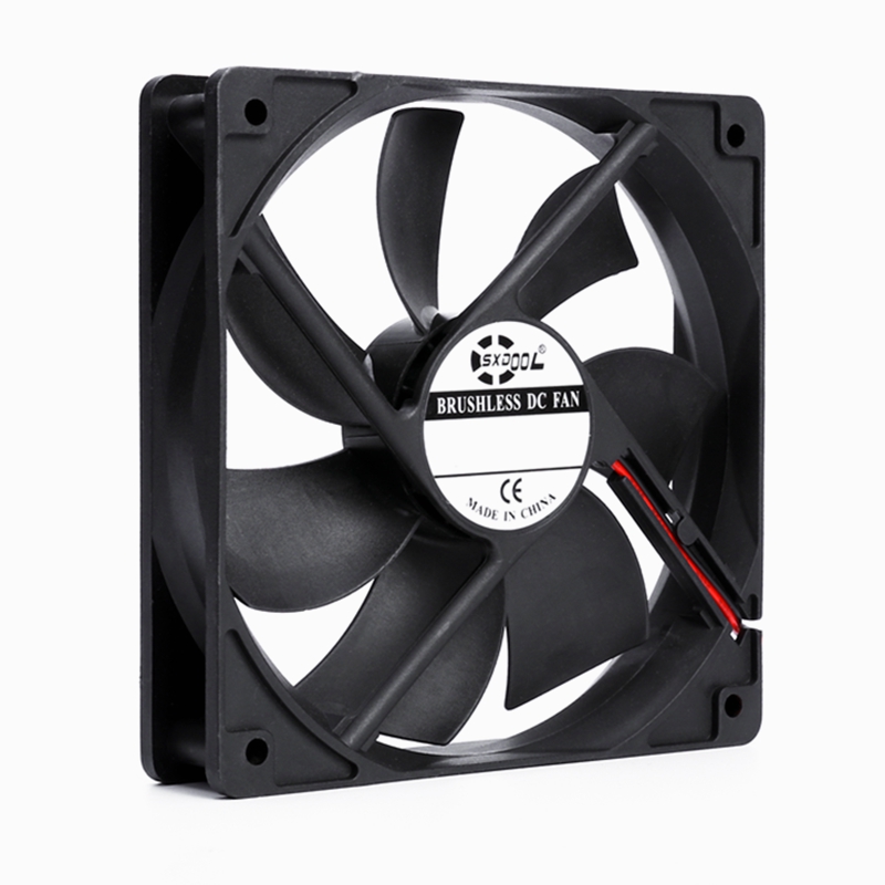
Historically, cabinet ventilation was treated as an unmonitored auxiliary function—fans ran continuously at fixed speeds, and their failures were only discovered after the cabinet overheated and critical machinery shut down. Today, high-availability manufacturing requires an active, integrated approach to thermal management. By interfacing intelligent cooling fans directly with the central PLC, industrial engineers can implement real-time speed monitoring, dynamic temperature mapping, and multi-stage fail-safe emergency sequences. This article examines the electrical, thermodynamic, and logical frameworks required to integrate advanced fan monitoring into PLC-controlled industrial automation systems, utilizing SXDOOL‘s high-performance PWM-controlled series.
1. Core Principles of PLC-Integrated Speed Monitoring
To transition from passive cooling to intelligent thermal control, the PLC must have real-time visibility into the mechanical health and speed of each cooling fan. This is accomplished by utilizing 3-wire and 4-wire DC fans equipped with active signal feedback.
        3-WIRE FAN PINOUT                             4-WIRE FAN PINOUT
    +-----------------------+                     +-----------------------+
    |  [1] VCC (Power)      |                     |  [1] VCC (Power)      |
    |  [2] GND (Ground)     |                     |  [2] GND (Ground)     |
    |  [3] FG (Tachometer)  |                     |  [3] FG (Tachometer)  |
    |                       |                     |  [4] PWM (Control)    |
    +-----------------------+                     +-----------------------+
- 3-Wire Fans: These units provide power (VCC, GND) and a third wire carrying the FG (Frequency Generator) tachometer signal. While speed can be measured, controlling the fan’s speed requires the system to vary the analog DC supply voltage (voltage-level modulation), which can restrict the minimum starting voltage and degrade motor efficiency.
- 4-Wire Fans: This is the gold standard for industrial automation. The fan receives a constant DC voltage (typically 12VDC or 24VDC) on pins 1 and 2, allowing the internal motor drive electronics to remain fully powered and responsive. Pin 3 provides the FG tachometer signal, while Pin 4 accepts a PWM (Pulse-Width Modulation) input to adjust the fan’s rotational speed from 0% to 100% duty cycle, maintaining peak motor torque and efficiency even at ultra-low speeds.
1.1 Signal Conditioning and PLC Input Interfacing
The FG signal generated by the fan’s internal Hall-effect sensor is typically an open-collector output. In an open-collector configuration, the fan’s internal transistor acts as a solid-state switch that pulls the signal line to Ground (GND) twice per revolution. To read this signal, an external pull-up resistor must be connected to a reference voltage.
In industrial panels, PLCs operate on 24VDC logic levels. Interfacing a fan’s open-collector output to a standard 24V digital input card requires a signal conditioning circuit to protect the fan’s internal circuitry and ensure reliable pulse edge detection.
                 PLC INTEGRATION WIRING SCHEMATIC (4-WIRE FAN)

    +---------------------+
    |  +24VDC DC Bus      |------+-------------+
    +---------------------+      |             |
                                 |             /
                                 |             \  Pull-Up Resistor
                                 |             /  (e.g., 2.2 kOhm)
                                 |             \
                                 |             |
    +---------------------+      |  (Pin 3)    +---------> [PLC High-Speed Input]
    |  SXDOOL 4-Wire Fan  |------|-- FG Signal ------------> (Tachometer pulse)
    |                     |      |
    |                     |------|-- PWM Input <---------- [PLC Analog/PWM Output]
    |                     |      |  (Pin 4)                 (0-10V to PWM converter)
    |                     |      |
    |                     |------+-- VCC (Pin 1)
    |                     |      |
    |                     |------+-- GND (Pin 2)
    +---------------------+      |
                                 v
                            System Ground
The frequency of the generated pulse train (fpulse) is directly read by the PLC’s integrated High-Speed Counter (HSC) input card. The PLC’s internal ladder logic or structured text program then calculates the exact fan rotational speed using the following mathematical formula:
RPM = 60 · fpulse / Pppr
Where:
- fpulse is the pulse frequency measured by the High-Speed Counter in Hertz (Hz).
- Pppr is the number of pulses generated per revolution by the fan’s Hall-effect sensor (standard SXDOOL industrial fans utilize Pppr = 2).
If the PLC registers 100 Hz on the high-speed counter:
RPM = (60 · 100) / 2 = 3000 RPM
2. Enclosure Temperature Mapping and Sensor Fusion
To execute smart speed control, the PLC must correlate fan speed feedback with thermal data from within the enclosure. Air within an automation cabinet behaves according to fluid dynamics, creating localized micro-climates. Due to the stack effect (natural convection), hot air rises, resulting in thermal stratification.
To achieve complete thermal visibility, engineers implement sensor fusion—deploying multiple temperature sensors (such as PT100/PT1000 RTDs or Type-K thermocouples) at strategic heights inside the cabinet:
- Sensor 1 (Intake Air Temperature): Placed at the bottom of the enclosure near the fresh-air intake louver to monitor the ambient factory floor temperature.
- Sensor 2 (Core Processing Zone): Positioned in the center of the cabinet, near the PLC rack and sensitive signal conditioning modules.
- Sensor 3 (Exhaust/Hot-Spot Zone): Mounted at the very top of the enclosure, immediately above the VFD heatsinks and auxiliary power supplies, where thermal accumulation is most severe.
                   CABINET THERMAL STRATIFICATION PROFILE

       +-------------------------------------------+
       |  [Sensor 3: Exhaust Zone]     (> 55°C)    |  <--- Hot Air Pocket
       |    +-------------------------+            |
       |    |  VFD Heatsinks          |            |
       |    +-------------------------+            |
       |                                           |
       |  [Sensor 2: Core Zone]        (35-45°C)   |  <--- Moderate Zone
       |    +-------------------------+            |
       |    |  PLC & Analog Cards     |            |
       |    +-------------------------+            |
       |                                           |
       |  [Sensor 1: Intake Zone]      (< 30°C)    |  <--- Cool Entry Zone
       +-------------------------------------------+
The PLC inputs these temperatures via analog input cards. A closed-loop PID (Proportional-Integral-Derivative) control algorithm runs on the PLC CPU, continuously calculating the required fan speed based on the worst-case temperature reading (typically Sensor 3).
If the top exhaust temperature climbs, the PLC ramps up the duty cycle of the SXDOOL 4-wire PWM fans, adjusting the airflow dynamically to match the current thermal load rather than running the fans at 100% capacity continuously. This dynamic scaling minimizes energy consumption, reduces filter clogging rates, and extends the mechanical service life of the fan bearings.
3. Fail-Safe Operations: Fan Failure Triggers and Emergency Stop Sequences
The ultimate benefit of PLC-integrated monitoring is the ability to execute graceful, automated fail-safe sequences when a cooling component fails. Standard industrial fans can suffer from locked-rotor conditions (caused by foreign debris, wire interference, or bearing failure) or rotational degradation (gradual mechanical wear).
3.1 Locked-Rotor Protection
SXDOOL PWM fans feature built-in electronic locked-rotor protection. If the impeller is physically blocked and ceases to rotate, the fan’s internal driver IC immediately cuts the drive current to the stator windings, preventing electrical overheating and winding burnout. The driver then attempts an auto-restart cycle every 3 to 5 seconds by applying a low-current pulse to check if the obstruction has cleared.
Simultaneously, the open-collector RD pin or FG pin transitions to a continuous static high-impedance state, alerting the PLC of the fault.
3.2 Automated Multi-Stage Fail-Safe Sequences
When the PLC detects that a fan’s RPM has dropped below 20% of its commanded speed or that the RD signal is active, it does not immediately trip the main circuit breaker. Instead, it executes a highly coordinated, multi-stage safety protocol programmed into its logic:
     [FAN FAILURE DETECTED]
               |
               v
      +----------------------------------+
      | STAGE 1: Visual/Audible Alarms   | ---> Flash stack lights, push HMI warning
      +----------------------------------+
               | (Temp Continues to Rise)
               v
      +----------------------------------+
      | STAGE 2: Automated Load Shedding | ---> Reduce VFD cycle times/current limits
      +----------------------------------+
               | (Temp Exceeds Threshold)
               v
      +----------------------------------+
      | STAGE 3: Controlled Deceleration | ---> Ramp down heavy motors safely
      +----------------------------------+
               | (Critical Safety Limit)
               v
      +----------------------------------+
      | STAGE 4: E-Stop / Contactor Trip | ---> Disengage main power, keep fans running
      +----------------------------------+
- Stage 1: Warning and Telemetry Dispatch (Immediate) — The PLC activates a flashing amber stack light on the machine cell, sounds an acoustic alarm, and logs a fault code in the plant SCADA/HMI system (e.g., “M044: Enclosure Exhaust Fan A – Rotational Stall Detected”). This notifies maintenance technicians to schedule a filter and fan replacement before thermal limits are crossed.
- Stage 2: Active Load Shedding (If Cabinet Temp > 48°C) — If the cabinet temperature continues to rise due to the loss of forced ventilation, the PLC initiates a software-driven thermal mitigation mode. It commands the VFDs and servo drives to reduce their switching frequencies (e.g., from 8 kHz to 4 kHz) or caps the maximum motor acceleration rates. This “load-shedding” reduces switching losses in the IGBT modules, lowering internal heat generation while keeping the production line running at a degraded speed.
- Stage 3: Controlled Deceleration (If Cabinet Temp > 55°C) — If the temperature reaches the critical thermal safety margin of the drive electronics, the PLC commands a controlled stop sequence of all heavy machinery. Stopping high-inertia motors immediately via a rapid, controlled deceleration ramp prevents massive regenerative energy surges back into the VFD DC bus—which would generate excessive peak heatsink temperatures.
- Stage 4: Emergency Stop and Contactor Trip (If Cabinet Temp > 62°C) — At the final safety threshold, the PLC opens the safety relay loop, de-energizing the main power contactors feeding the drives. Crucially, the 24VDC auxiliary power supply remains active, keeping the PLC, telemetry sensors, and any functional backup exhaust fans running to rapidly dissipate the residual, stagnant heat trapped in the cabinet.
4. Mechanical & Electrical Durability: Japan NMB Dual Ball Bearings
The environment of a factory floor is often highly hostile. Air contains aerosolized cutting fluids, oil mist, fine plastic dust, and metallic particulates. Traditional fans with sleeve bearings or low-grade ball bearings degrade rapidly under these conditions.
- Sleeve Bearings (High Vulnerability): Sleeve bearings rely on a thin film of liquid lubricant. At high operating temperatures, the oil evaporates or migrates out of the sleeve, leading to high mechanical friction, rotor oscillation, and eventual mechanical lockup within 10,000 to 20,000 hours of continuous operation.
- Japanese NMB Dual Ball Bearings (Extreme Longevity): SXDOOL integrates premium NMB dual ball bearings into its industrial PWM series. These bearings feature deep-groove, hardened steel races and precision-ground spheres designed to handle radial and axial thrust loads simultaneously.
Equipped with specialized high-temperature, hydrophobic synthetic lubricants and high-integrity mechanical seals, NMB bearings operate reliably for over 70,000 hours of continuous 24/7 operation—even at ambient cabinet temperatures of 70°C. This mechanical robustness significantly reduces the frequency of locked-rotor events, providing the physical reliability to match the PLC’s logical fail-safe routines.
5. SXDOOL PWM-Controlled Industrial Series
SXDOOL’s range of industrial fans is specifically engineered for seamless integration with modern PLC and SCADA platforms. Key technical advantages include:
- EMC-Shielded Motor Drivers: High-frequency PWM switching can generate significant electromagnetic interference (EMI) that can interfere with sensitive PLC analog input signals (like 4-20mA or 0-10V loops). SXDOOL fans feature integrated copper shielding and low-pass filtering on the driver board, suppressing both radiated and conducted emissions in compliance with IEC 61000-6-2 (Industrial Immunity).
- Wide Voltage Range Tolerance: Industrial 24V power rails can fluctuate significantly depending on the load profile of adjacent heavy motors, dropping to 18VDC or spiking to 30VDC during regenerative braking events. SXDOOL’s 24V fans operate across a wide input range (16VDC to 28VDC), with built-in over-voltage and transient voltage suppression (TVS) diodes.
- High-Static-Pressure Blades: Enclosure ventilation requires pushing air through highly restrictive pathways, including intake louvers, fine-mesh dust filters, and densely routed wire ducts. SXDOOL utilizes CFD-designed, fiber-reinforced PBT impellers that maintain high static pressure curves, preventing flow stall under heavy system impedance.
6. Factory-Floor Case Study: Automotive Assembly Line Panel Upgrade
At a major automotive manufacturing facility, a robotic spot-welding cell suffered repeated, unexplained downtime. The cell’s master control panel, housing six high-power servo drives, experienced frequent “Over-Temperature Faults” on the main drives during summer months. The panel relied on standard, unmonitored AC axial fans. If a fan filter became clogged or a fan motor failed, the first indication was a complete system shutdown mid-cycle, stalling the entire assembly line at a cost of over $15,000 per incident.
                  UPGRADED AUTOMATION CABINET THERMAL CONTROL

    +-------------------------------------------------------------+
    |  [SXDOOL Exhaust Fan A] ------------ [SXDOOL Exhaust Fan B]  |
    |      (FG Speed Feedback)                (FG Speed Feedback) |
    |            \                                  /             |
    |             +--------------+  +--------------+              |
    |                            |  |                             |
    |                            v  v                             |
    |                   +-------------------+                     |
    |                   |  Siemens S7-1200  |                     |
    |                   |  PLC Control CPU  |                     |
    |                   +-------------------+                     |
    |                            ^                                |
    |                            | (Analog Temps)                 |
    |                            |                                |
    |  [Sensor 1 (Bottom)] ------+------ [Sensor 3 (Top Zone)]    |
    +-------------------------------------------------------------+
The Solution:
The plant engineers retrofitted the cabinet with SXDOOL 24V 4-wire PWM-controlled fans and integrated them with a Siemens S7-1200 PLC:
- The open-collector FG signals of the fans were connected to the S7-1200’s high-speed counter inputs via simple optoisolated level-shifters.
- Three PT100 sensors were installed to monitor the bottom, middle, and top cabinet zones.
- The PLC was programmed with a PID block that dynamically adjusted the fans’ speed between 30% and 100% based on the highest temperature sensor.
- An alarm threshold was established: if any fan’s RPM dropped below 1500 RPM while commanded to run at 100% PWM, a warning was generated on the main SCADA dashboard.
The Results:
During the first year of operation, the PLC successfully detected a fan failure caused by a technician accidentally pinching an internal wiring harness. The system immediately generated a Stage 1 alarm, allowing the maintenance team to swap the fan during a scheduled lunch break without halting production.
Over a 24-month post-retrofit period, the robotic welding cell experienced zero thermal shutdowns, representing a 98% reduction in heat-related cabinet downtime and saving the facility hundreds of thousands of dollars in lost manufacturing capacity.
7. Technical Integration Parameters Reference
To assist system integrators in specifying fan-to-PLC interfaces, the following table summarizes the typical hardware and logic configurations:
| Parameter | 3-Wire Fan Integration | 4-Wire Fan Integration |
|---|---|---|
| Primary Connection Pins | VCC, GND, FG (Tachometer) | VCC, GND, FG (Tachometer), PWM (Control) |
| Speed Feedback Signal | Open-Collector square-wave (FG) | Open-Collector square-wave (FG) |
| PLC Input Requirement | Digital Input with High-Speed Counter (HSC) | Digital Input with High-Speed Counter (HSC) |
| Speed Control Method | Analog DC voltage-level scaling (12V to 24V) | Digital PWM signal duty cycle adjustment (0-100%) |
| PWM Input Specification | N/A | 5V or 10V logic levels, typical frequency 25kHz |
| Required Pull-Up Resistor | 1 kΩ to 4.7 kΩ (Based on PLC input impedance) | 1 kΩ to 4.7 kΩ (Based on PLC input impedance) |
| Locked Rotor Protection | Driver IC automatic shut-off and auto-restart | Driver IC automatic shut-off and auto-restart |
| Recommended Bearings | Japan NMB Dual Ball (24/7 factory rating) | Japan NMB Dual Ball (24/7 factory rating) |
| PLC Software Blocks | Frequency-to-RPM calculation block | Frequency-to-RPM block + PWM output PID control loop |
Conclusion: The Integrated Thermal Path
For modern industrial automation, cooling is no longer a peripheral concern—it is a core parameter of system reliability. Integrating high-performance 4-wire PWM fans with the cabinet’s main PLC enables a shift from reactive firefighting to proactive, software-defined thermal defense.
Through the precise combination of multi-point temperature mapping, high-speed RPM pulse tracking, and carefully designed multi-stage emergency stop sequences, engineers can guarantee that critical controllers and drive units remain within their optimal operating zones. Utilizing SXDOOL’s PWM series—backed by the mechanical excellence of Japanese NMB dual ball bearings—ensures that your thermal protection is as intelligent, precise, and durable as the automation systems it cools.