Blog
Cooling Fan Acoustics for MRI and CT Support Systems

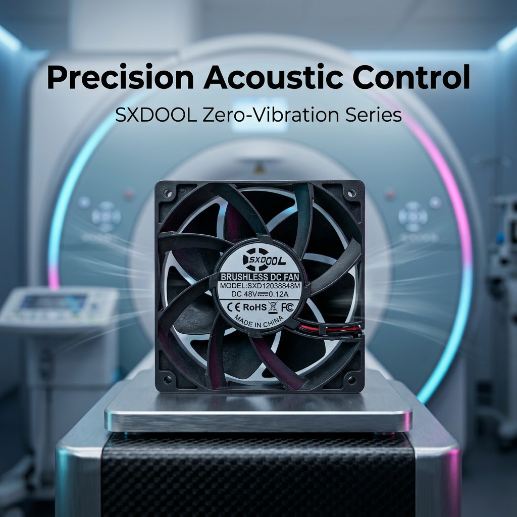
Medical imaging support electronics need controlled temperatures without adding distracting tonal noise or structural vibration near patients and operators. The acoustic result depends on the complete airflow system: motor commutation, bearings, blade-passing frequency, grille turbulence, duct resonance and panel vibration can all contribute.
A fan described as low noise in free air may become objectionable behind a restrictive grille or when mounted to a resonant panel. Selection should therefore combine the required pressure-airflow operating point with frequency-sensitive acoustic and vibration measurements in the representative assembly.
Engineering workflow
- Characterize the noise target. Define sound pressure, measurement distance, room background and any sensitive frequency bands rather than using one unqualified dBA value.
- Reduce aerodynamic restriction. Use generous inlet area, smooth transitions and adequate clearance from grilles and heat sinks to limit turbulence and blade interaction.
- Control structural transmission. Review mounting stiffness, panel modes, imbalance and isolation. Isolation must still maintain secure fastening, grounding and serviceability.
- Optimize the speed strategy. Use the lowest validated speed that maintains temperature margin, with slow ramps and hysteresis to avoid repeated audible speed changes.
- Coordinate electrical compatibility. Confirm PWM, FG/RD, grounding and EMC behavior with the medical equipment engineering team; the complete device remains subject to its own validation.
Technical decision table
| Design item | Engineering meaning | Evidence or action | Acceptance focus |
|---|---|---|---|
| Broadband airflow noise | High velocity and turbulence | Sound spectrum and airflow-path inspection | Lower restriction or reduce speed |
| Blade-passing tone | Rotor/stator or grille interaction | Frequency spectrum versus RPM | Change spacing, grille or operating speed |
| Motor/commutation tone | Drive electronics and magnetic forces | Near-field spectrum | Evaluate exact motor/control variant |
| Structure-borne vibration | Imbalance or resonant mounting | Accelerometer and panel inspection | Balance, stiffen or isolate appropriately |
| Control hunting | Narrow thresholds or poor sensor location | Speed and temperature trend | Add hysteresis and slower ramps |
Validation in the finished system
Measure temperature, fan speed, sound and vibration together at minimum, nominal and peak thermal load. Repeat with production grilles, filters, ducts and mounting hardware. Acoustic validation should be performed in a controlled environment and should not be confused with medical-device EMC, safety or clinical compliance, which remain responsibilities of the finished-equipment manufacturer.
Information to include in the OEM RFQ
- Required airflow and pressure at each thermal operating mode
- Sound target, distance, test environment and sensitive frequency bands
- Frame, mounting, grille, duct and panel construction
- Voltage, PWM range, FG/RD signal and cable/connector
- Ambient range, duty cycle and acceptable component temperatures
- Sample plan and device-level acoustic, EMC and safety validation
Frequently asked engineering questions
Is the fan with the lowest catalog dBA always the best choice?
No. Catalog conditions may differ, and a lower free-air value may not remain lower at the required static pressure or inside the final enclosure. Compare at the same operating point and mounting condition.
Can soft mounts eliminate all vibration?
No. Isolation can reduce transmission in selected frequency ranges, but poor balance, cable bridges, loose hardware or an unsuitable mount can still transmit vibration. Secure installation and measured verification are required.
Does using a low-noise fan make the medical imaging system compliant?
No. Fan selection supports thermal and acoustic design, while the finished equipment manufacturer remains responsible for all applicable safety, EMC, performance and regulatory requirements.
Work with SXDOOL engineering
SXDOOL supports factory-direct OEM/ODM cooling fan projects with application review, dynamic balancing and 100% end-of-line testing for the agreed production specification. Review Cooling solutions for MRI and CT scanners and Contact SXDOOL engineering, then send the operating point, drawing, electrical interface and expected quantity through the contact page or email david@sxdool.com.