Blog
UPS Cooling for Power Electronics and Battery Systems

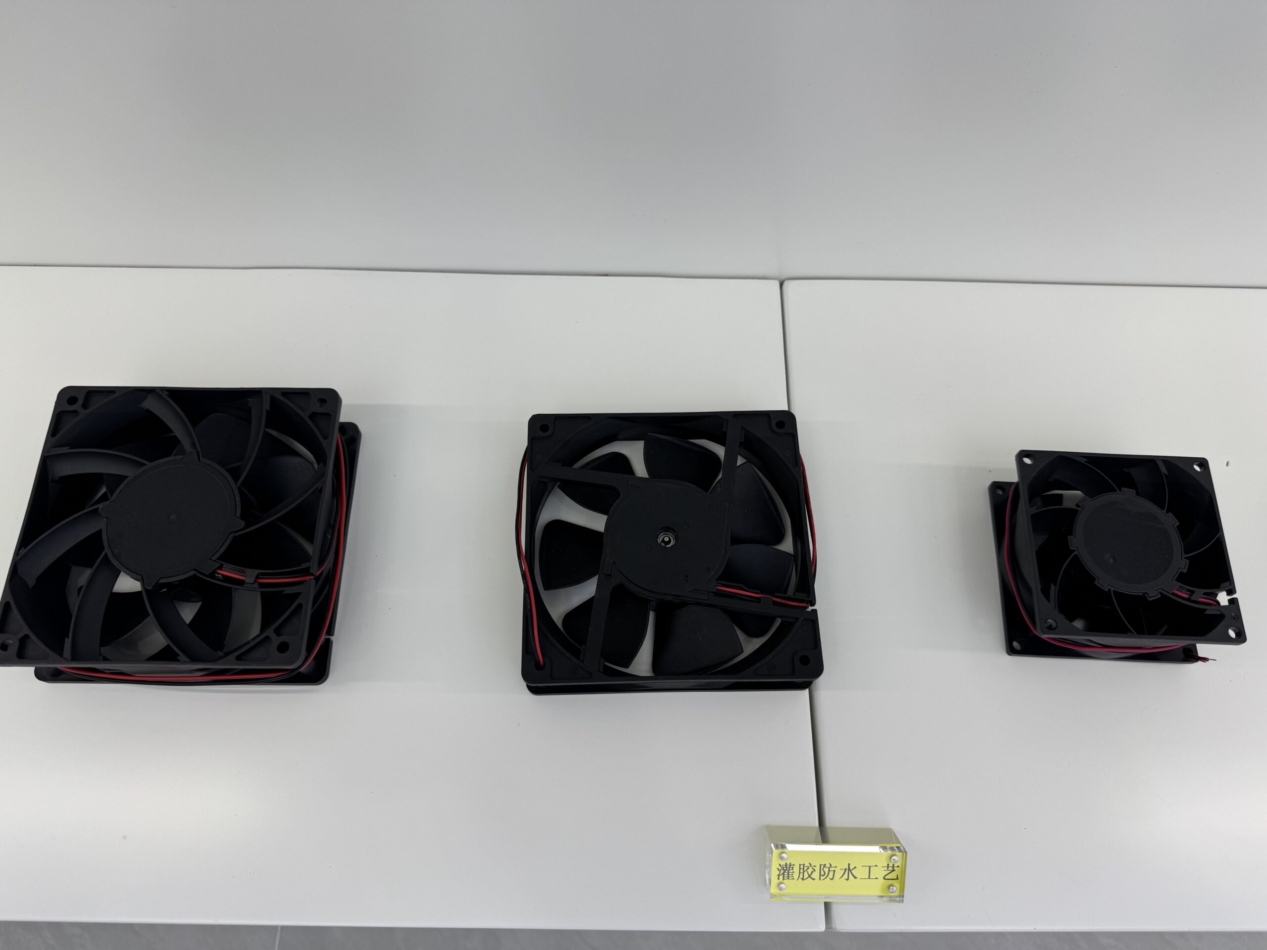
An uninterruptible power supply must manage heat from rectifiers, inverters, transformers, filters, switching devices and batteries while remaining available during utility disturbances. Fan selection therefore cannot be based on free-air airflow alone. The useful operating point is the airflow delivered through the actual cabinet resistance at the highest credible thermal load.
A robust UPS cooling architecture separates normal heat removal from fault response. It also defines what happens during battery operation, bypass mode, a blocked filter and the loss of one fan. The objective is not simply a low internal temperature; it is controlled component temperature with measurable airflow, predictable alarms and serviceable fan modules.
Engineering workflow
- Map the heat sources. List losses for each power stage at rated load, overload and charging conditions. Include localized hot spots around semiconductors, magnetics and bus connections.
- Define the airflow path. Position inlets and outlets so cool air reaches the highest-risk components before it mixes with exhaust air. Prevent short-circuit recirculation between adjacent vents.
- Calculate the pressure budget. Add filter, grille, heat-sink, duct and internal obstruction losses. Compare the resulting system curve with the candidate fan P-Q curve.
- Design fault tolerance. For critical installations, evaluate N+1 fan capacity, hot-swap access, FG or RD monitoring, and the remaining thermal margin after one fan stops.
- Coordinate controls. Use PWM or voltage control only within the fan specification. Define minimum speed, startup boost, hysteresis and a safe full-speed state if the control signal fails.
Technical decision table
| Design item | Engineering meaning | Evidence or action | Acceptance focus |
|---|---|---|---|
| Rectifier and inverter | High switching and conduction losses | Directed airflow across heat sinks | Airflow at system pressure, inlet temperature |
| Transformer and inductors | Core and winding temperature rise | Continuous air exchange around windings | Hot-spot temperature, obstruction clearance |
| Battery compartment | Temperature-sensitive life and charging behavior | Controlled, code-compliant ventilation strategy | Battery supplier limits, enclosure safety review |
| Input/output filters | Distributed heat with restrictive geometry | Pressure-capable airflow through dense components | Static pressure, filter loading |
| Fan subsystem | Single-point failure risk | Redundancy and monitored operation | FG/RD signal, current, connector, service access |
Validation in the finished system
Qualification should include rated load, overload, high ambient, low-line and high-line input, charging, battery discharge, bypass, clean and loaded filters, and a simulated fan failure. Measure temperatures at the component hot spots rather than relying on one cabinet-air sensor. Confirm startup current, acoustic behavior, alarm thresholds and recovery after power cycling.
Information to include in the OEM RFQ
- Cabinet dimensions, inlet and outlet drawings, and component layout
- Heat loss by operating mode and maximum allowable component temperatures
- Required airflow or measured system-resistance curve
- Supply voltage, current limit, PWM range, FG/RD signal and connector
- Ambient range, altitude, dust exposure, filter condition and duty cycle
- Redundancy, hot-swap, service-life and qualification requirements
Frequently asked engineering questions
Should a UPS use an AC, DC or EC fan?
The choice depends on the available power rail, control architecture, efficiency target and required operating point. DC fans integrate easily with low-voltage controls, while EC fans can provide efficient variable-speed operation from AC input. Compare complete electrical and control requirements, not motor type alone.
Does N+1 redundancy mean every fan can run slowly?
Not automatically. The remaining fans must still deliver the required airflow against cabinet resistance after one fan fails. The control system also needs a verified alarm and a thermal response that prevents components from exceeding their limits.
Can one temperature sensor control the whole UPS?
A single sensor can miss local hot spots or respond too slowly. Sensor placement should reflect semiconductor, magnetics and inlet-air conditions, and the final control map should be verified with instrumented thermal testing.
Work with SXDOOL engineering
SXDOOL supports factory-direct OEM/ODM cooling fan projects with application review, dynamic balancing and 100% end-of-line testing for the agreed production specification. Review 120 mm DC cooling fan platforms and SXDOOL Fan Selector, then send the operating point, drawing, electrical interface and expected quantity through the contact page or email david@sxdool.com.