Blog
Thermal Management of High-Power UV Lamps in Lithography Systems

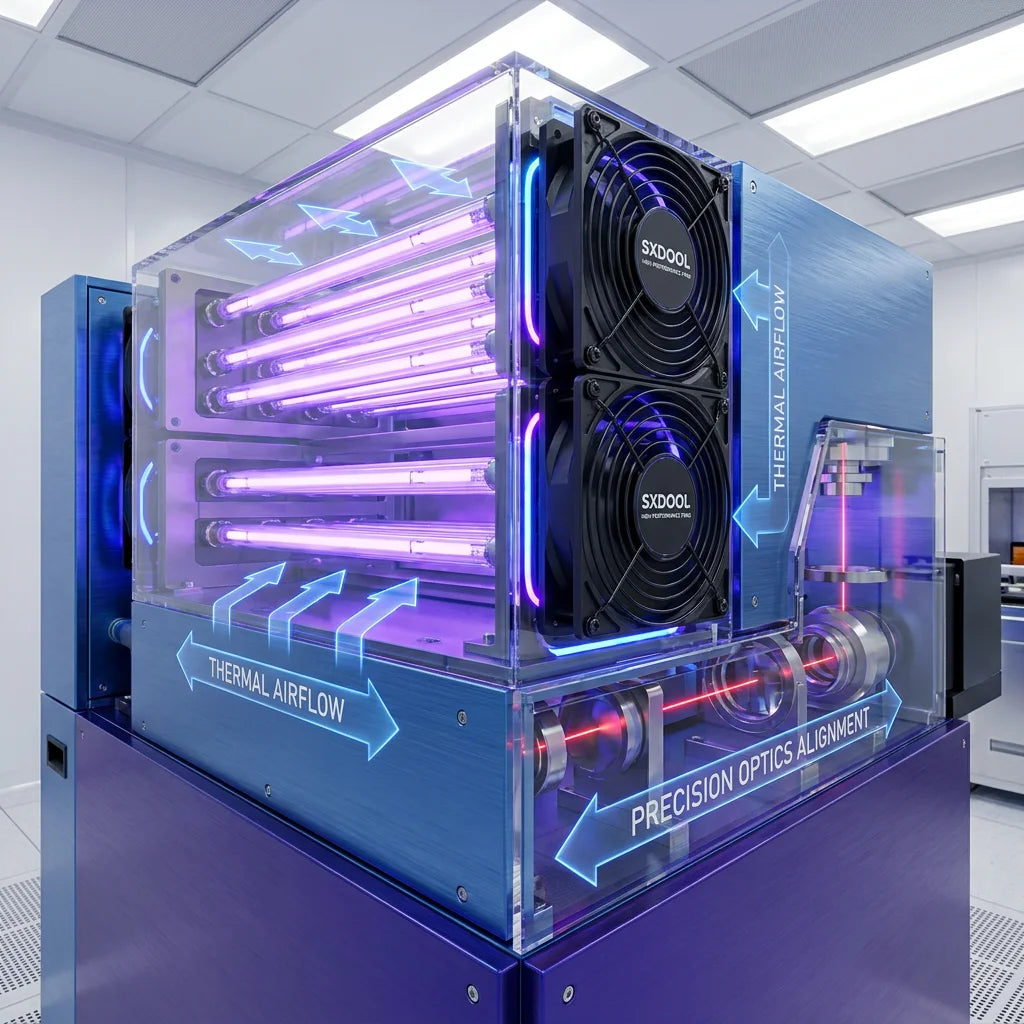
Cooling requirements for UV lamp assemblies
Introduction
UV lamp assemblies can impose thermal, contamination and vibration constraints on the surrounding equipment. Start with the exact light-source and equipment specifications so that fan selection addresses the intended air path and operating conditions.
Cooling selection for a UV lamp assembly starts with the equipment manufacturer’s temperature limits, permitted air path and maintenance requirements. Fan control, vibration and contamination must be evaluated for the actual installation; this guide does not establish that any SXDOOL model is qualified for a lithography tool.
Separate the lamp assembly from other lithography cooling systems
Identify whether the fan serves a lamp housing, an electronics compartment or an external heat exchanger. A cooling arrangement approved for one of these locations should not be assumed suitable for another. Follow the exact light-source manufacturer’s cooling and ventilation instructions.
Do not treat UV lamps, DUV laser systems and EUV sources as interchangeable applications. ASML describes the EUV light path as a high-vacuum environment; this is not a claim that an ordinary air-cooling fan can operate in that optical path.
Define the consequences to test
Include the equipment manufacturer’s limits for lamp housing temperature, nearby electronics, optical stability and ventilation. Check the specified response to reduced airflow or fan failure. Do not infer process accuracy or lamp life from fan selection alone.
Technical Deep Dive: Maintaining Optical Alignment through Thermal Control
Specify the allowable temperatures and thermal drift at the lamp assembly, electronics and sensitive mounts. Those limits belong to the equipment design and cannot be inferred from a fan’s free-air rating.
Precise Thermal Gradients
If the selected fan supports speed control and a feedback signal, verify the electrical interface, minimum stable speed, starting behaviour and fault response against its approved specification. A PWM input and a speed-feedback output are separate functions. Confirm the assembled thermal response at the permitted operating speeds.
Airborne Molecular Contamination (AMC) Management
Contamination requirements should identify the surfaces at risk, the permitted air path, filtration and allowable materials. Review the fan as part of that complete air-handling design.
Where the fan shares air with contamination-sensitive components, request the exact material, lubricant and outgassing requirements from the equipment manufacturer. Do not infer silicone-free construction or chemical-filter performance from a general fan description.
Engineering for Compact Assemblies: High-Static Pressure Solutions
Modern lithography tools are incredibly dense. Light sources are surrounded by shielding, reflectors, and complex beam-delivery optics. This creates a high-impedance environment—meaning air cannot flow easily.
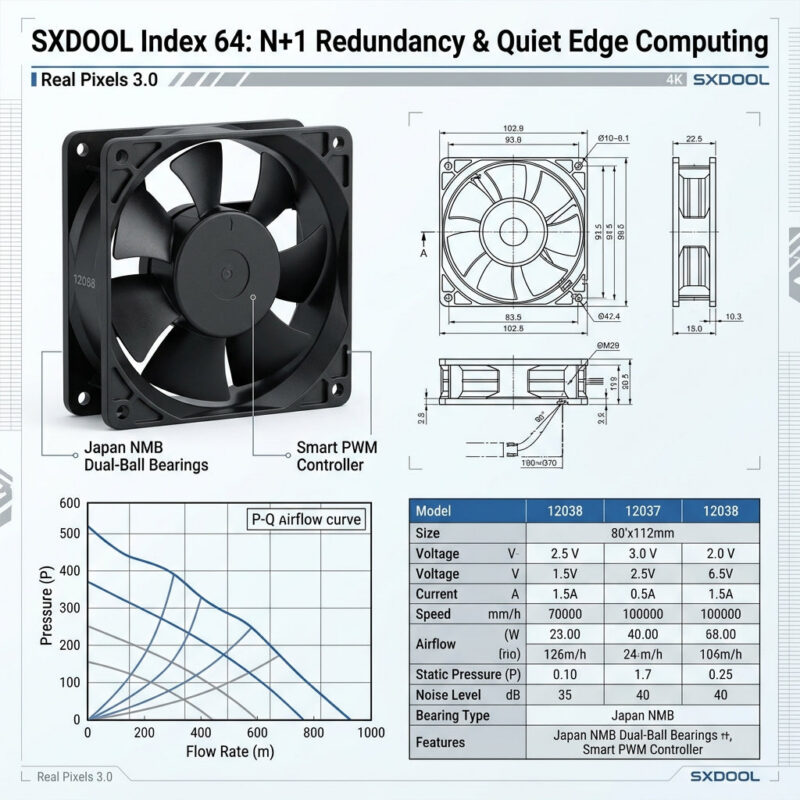
For a restricted air path, compare the candidate fan’s pressure–airflow curve with the resistance of the complete assembly, including filters, guards and ducts. Verify the operating point under the required service condition. Blade shape or free-air flow alone does not establish performance in the lamp housing.
Reliability near a UV source
Record whether the fan is exposed directly to UV, ozone, heat or cleaning chemicals, and how the equipment shields it. Bearing type, lubricant, plastics and cable materials must be checked for the selected model and exposure conditions. A bearing brand alone does not establish radiation resistance or application life.
Mitigating Micro-Vibration in Sensitive Optics
Fan vibration can reach adjacent equipment through its mounts. Evaluate the relevant operating speeds and mounting arrangement against the equipment’s permitted vibration limits.
Evaluate vibration and noise in the installed assembly, including mounting stiffness, speed range and nearby optical components. Specify acceptance limits and request model-specific balancing or vibration records where required; no balance grade or isolation performance is established by this article.
Request a model-specific cooling review
Send SXDOOL the lamp or equipment model, fan location, available space, supply voltage, required pressure and airflow, inlet temperature, duty cycle, contamination constraints, permitted vibration and signal interface. Include the original fan specification when evaluating a replacement.
Use the selected model’s approved drawing, datasheet and representative assembly tests to decide suitability. This guide does not certify cleanroom use, radiation resistance, a particular bearing brand or compatibility with an existing lithography tool.