Blog
Cooling Fans for DC Fast Charger Power Modules

Select a fan for an air-cooled DC charging module at the airflow and pressure the complete charger requires. Start with the module’s loss map, inlet conditions, heat-sink path and controller interface. A high free-air rating or a charger power rating does not prove that a fan will keep the power electronics within their temperature limits.
This guide is for OEM evaluation of a fan in a new or redesigned power-module assembly. It also explains which requirements to collect before requesting an SXDOOL candidate review. For a field replacement in an existing charger, use the equipment manufacturer’s approved part and service procedure.
Technical sources checked: 25 October 2026.
Separate the module air path from the charger enclosure
Map the components that dissipate heat during conversion: switching devices and rectifiers, magnetic components, busbars and other resistive connections. Identify the temperature-sensitive components along the same path, including capacitors and control electronics. Record the relevant losses and allowable temperatures over the charging profile; the electrical power delivered to the vehicle is not the module’s waste heat.
Mark where the fan sits relative to the module inlet, heat sinks and outlet. Then include the cabinet’s filters, guards, duct turns, cable congestion and nearby modules. A module may draw air that is already warm from another bay, or exhaust into a space that allows recirculation. The fan’s inlet temperature and installed airflow must therefore be checked in the complete enclosure.
A liquid-cooled cable or dispenser does not establish how the conversion module is cooled. Use the exact module documentation to identify its thermal architecture. Keep module cooling, cabinet ventilation and the air side of a liquid-cooling radiator as separate design tasks.
Use the module’s operating limits to define the test
As a concrete equipment example, Infypower identifies its REG1K0100G2 as a fan-cooled DC charger power module. Its technical table specifies power derating above a defined ambient condition, non-condensing humidity, an altitude limit and several noise modes. Those are requirements for that Infypower configuration; they are not SXDOOL fan specifications or evidence that an SXDOOL fan is approved for it.
The selection implication is to record the module revision and operating mode before testing. Confirm what its temperature measurement refers to, which output is allowed under those conditions, and how its overtemperature protection recovers. Test the intended charging duty and acoustic mode together instead of claiming full output from a fan-only airflow measurement.
Find the operating point with the service air path
Ask for the pressure-flow curve for the exact offered fan configuration and compare it with the resistance of the complete path. Maximum airflow and maximum static pressure are different endpoints, not a simultaneous working condition. SANYO DENKI’s fan-selection guidance explains the relationship between installed airflow and system resistance, and calls for confirmation through an installation test.
| Condition | What to check in the assembled charger |
|---|---|
| Sustained charging load | Heat-sink and critical component temperatures after stabilization, with the declared input, output, inlet temperature and control mode. |
| Filter service condition | Airflow and component temperatures at the agreed filter restriction. Define how maintenance is triggered before that condition becomes unacceptable. |
| Adjacent active modules | Inlet warming, exhaust recirculation and unequal airflow between bays; include the installed doors, baffles and unused-slot closures. |
| Reduced-speed or quiet operation | The permitted output, thermal margin and measured sound at the specified location. Include grille tones and structure-borne vibration. |
| Failed fan or lost signal | Detection, derating or shutdown response defined by the equipment design. Two installed fans alone do not demonstrate redundancy. |
Filter service is part of the design. For example, the ABB Terra DC Wallbox user manual, dated 15 November 2022, identifies front and top filters and requires periodic inspection, with replacement needs affected by environment and charging use. Follow the manual for the actual charger; this example does not set a universal service interval or authorize a fan substitution.
An SXDOOL candidate to investigate
SXD6038B24H-RDP is an existing exact-model reference for a configuration review. Its listing discusses a compact fan with speed-control and alarm considerations, making it a starting point for asking about a restricted electronics air path. Request the current released drawing, curve, electrical requirements and interface definition for the complete suffix before deciding whether to test it.
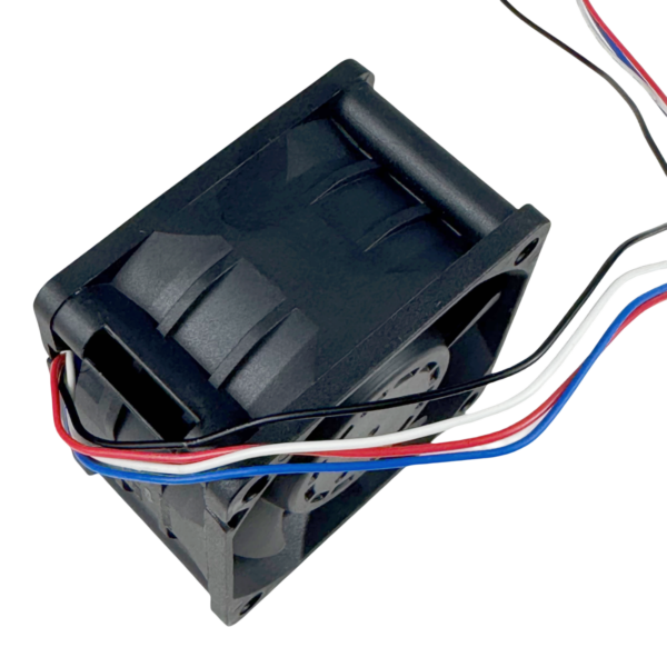
Compare the offered sample’s mounting envelope, airflow direction, supply range and startup demand with your module. Check whether the controller requires speed feedback, a stopped-fan alarm, or both. PWM control, tachometer feedback and an alarm output serve different functions; similar wire counts or connector shapes do not establish electrical compatibility.
Selection boundary: No installed DC charger test result is claimed for this candidate. Do not treat its model reference as a drop-in replacement for an Infypower, ABB or other OEM assembly. If a released curve, interface drawing or environmental qualification cannot be provided for the proposed configuration, keep it outside the approved bill of materials.
For exposed airflow, establish the water and contamination path through the enclosure. A fan-level protection claim cannot establish the charger’s ingress rating. Include condensation, dust, corrosive exposure, maintenance access and cable routing in the project requirements; confirm the applicable exact-model evidence through the technical document request page.
Information to send with a module cooling enquiry
- Charger architecture, module make and revision, heat-loss data, load profile and component temperature limits.
- Available mounting space, fan position and airflow direction, plus the heat-sink, filter and duct arrangement.
- Measured or estimated resistance at the target airflow, including the intended filter service condition.
- Fan supply range and startup budget; controller pinout, speed command and fault-response requirements.
- Module inlet conditions, altitude, contamination and condensation exposure, acoustic limit and service access.
Use these inputs to agree a sample configuration and acceptance test. Record the exact fan revision, filter condition, controller settings and measurement locations with each result so a later replacement can be assessed against the same conditions.
Request a DC charger module fan review
DC charger module fan questions
Can a higher static-pressure rating solve overheating by itself?
No. Review the actual operating point, inlet temperature, recirculation and heat transfer from the components to the air. A different fan can also change electrical demand, noise and controller behavior. Confirm the complete module under its specified load and environment.
Can a quiet mode use the same full charging output?
Only if the equipment documentation and thermal test support that combination. Lower speed changes airflow and pressure. Test the module in its intended mode and respect the permitted output and temperature limits.
Can an alarm wire replace the original fan’s speed feedback?
Do not assume so. A rotation alarm may report a state rather than measured speed. Confirm the released output circuit, normal and fault states, commanded-stop behavior, timing and controller thresholds for the exact fan.
Should a failed charger fan be replaced with a dimensionally similar fan?
A dimensional match is insufficient. Use the charger’s approved service part and procedure. For a new design, qualify the complete fan, mounting, harness, controller and thermal path before release.
Related selection scope: EV charger cooling architecture · DC fan product category · Fan selection inputs.