Blog
Low-Acoustic Noise Fans for Patient-Side Medical Imaging (MRI/CT)

Introduction
Modern diagnostic medical imaging—specifically Magnetic Resonance Imaging (MRI) and Computed Tomography (CT)—represents the pinnacle of non-invasive clinical diagnostics. However, these systems also present some of the most hostile thermal and acoustic environments in the biomedical field. The operation of high-power RF transmitters, rapidly switching gradient coils, and continuously spinning CT gantries generates immense thermal loads that must be dissipated immediately to maintain system stability, calibrate image accuracy, and prevent component degradation.
Traditionally, thermal management in these suites has relied on aggressive forced-air cooling. However, placing high-speed, noisy fans in close proximity to patients introduces significant problems. In MRI suites, the extreme acoustic noise from gradient coils (which can exceed 110 dBA due to Lorentz forces) already induces high levels of patient anxiety, which can lead to involuntary movement and ruined scans. Adding the persistent, high-frequency whine of cooling fans exacerbates this patient stress and can degrade the signal-to-noise ratio (SNR) of the imaging hardware.
For biomedical engineers, designing cooling solutions for patient-side imaging equipment requires balancing fluid dynamics, acoustics, vibration isolation, and electromagnetic compatibility (EMC). This article analyzes the engineering behind low-acoustic-noise cooling fans, examining acoustic signatures, structural vibration isolation, EMI/RFI shielding, high-precision bearings, and how next-generation EC fan technology is transforming medical imaging equipment design.
Thermal Challenges in MRI and CT Systems
To understand the cooling requirements, we must examine the specific subsystems within MRI and CT scanners that demand active thermal management.
Gradient Coil Cooling in MRI
In MRI systems, gradient coils are responsible for spatial encoding of the magnetic resonance signal. These coils are pulsed with hundreds of amperes of current at kilohertz frequencies, generating massive resistive heat. If gradient temperatures fluctuate, the local magnetic field homogeneity degrades, leading to geometric distortion and phase-encoding errors in the resulting images. Active airflow cooling must remain constant, continuous, and highly uniform across the gradient cylinder.
X-Ray Tube and Electronics Cooling in CT
CT scanners utilize a rotating gantry that houses the X-ray tube, high-voltage generator, and detector arrays. The X-ray tube operates under extreme thermal stress, with anode heat storage capacities often exceeding several million Heat Units (MHU). While the tube itself is typically oil-cooled, the circulating oil heat exchangers, RF amplifiers, and data acquisition systems (DAS) on the rotating gantry require rapid, high-pressure forced-air cooling. Because these fans spin along with the gantry at speeds up to 200 RPM, they must withstand immense centrifugal forces while maintaining ultra-quiet operation.
Acoustic Signature Analysis and Aeroacoustic Optimization
When selecting or designing a cooling fan for patient-side medical applications, simple decibel (dBA) ratings are insufficient. Engineers must conduct detailed acoustic signature analysis to identify and eliminate specific noise frequencies that contribute to patient discomfort and system resonance.
Understanding the Acoustic Spectrum
Fan noise is divided into two main categories:
- Broadband Noise: Caused by turbulent flow, vortex shedding at the blade trailing edges, and boundary layer separation. This exhibits a continuous spectrum and is psychoacoustically perceived as “pink noise,” which is relatively easy for the patient to tolerate.
- Tonal Noise (Discrete Peaks): Caused by the physical interaction of the rotating blade with stationary struts or nearby structures. This produces distinct spikes in the frequency spectrum at the Blade Pass Frequency (BPF) and its harmonics. Tonal noise is perceived as a highly irritating “whine” or “hum.”
In patient-side medical equipment, fans must be designed to suppress BPF peaks, smoothing the acoustic signature into a non-intrusive broadband profile.
Aeroacoustic Engineering
To minimize broadband and tonal noise, high-end medical fans utilize bionically optimized impellers. Features include:
- Winglets and Serrated Trailing Edges: Inspired by owl feathers, these structures break up large air vortices into smaller, less energetic turbulence cells, dramatically reducing vortex shedding noise.
- Forward or Backward Curved Aerofoil Blades: Designed using Computational Fluid Dynamics (CFD) to maintain laminar boundary layers across a wide operating range, minimizing stalling and associated low-frequency pressure pulsations.
Structural Vibration Isolation (low-vibration Engineering)
While airborne noise affects patient comfort, structure-borne vibration directly threatens image quality.
Imaging Artifacts and Resonance
In MRI, even microscopic mechanical vibrations (measured in microns or millimeters per second) transferred from a cooling fan to the scanner frame can modulate the static magnetic field or the gradient fields. This results in phase artifacts, ghosting, and a degraded Signal-to-Noise Ratio (SNR). In CT, high-frequency vibrations can cause pixel blurring on the detector array, compromising sub-millimeter spatial resolution.
Dynamic Balancing and Decoupling
To achieve “low-vibration” operation, medical cooling fans must meet the specified dynamic balancing targets:
- ISO 1940 Grade G1.0: Standard industrial fans are balanced to G6.3 or G2.5. Medical imaging applications require Grade G1.0 or even G0.4, meaning residual unbalance is virtually non-existent. This is achieved through automated, multi-plane micro-balancing processes during fan manufacturing.
- Elastomeric Decoupling: Fans must be physically isolated from the mounting chassis using specialized silicone or thermoplastic elastomer (TPE) dampers. These dampers are custom-formulated to have a natural resonance frequency well below the fan’s operating speed, ensuring that high-frequency motor and blade vibrations are completely absorbed rather than transmitted.
Electromagnetic (EMI) and Radiofrequency (RFI) Shielding
An MRI suite is a shielded environment; the scanner room acts as a Faraday cage to exclude external RF noise. Inside this room, the MRI receiver coils are sensitive to electromagnetic emissions in the megahertz range—specifically matching the Larmor frequency of hydrogen protons (e.g., 63.8 MHz at 1.5 Tesla, or 127.7 MHz at 3 Tesla).
The Danger of Brushless Motors
Standard brushless DC (BLDC) fans rely on electronic commutation, which generates high-frequency electromagnetic switching noise (EMI) and radiofrequency interference (RFI). If unshielded, this electrical noise bleeds directly into the MRI receiver circuitry, appearing as prominent “zipper” artifacts or bright lines across the diagnostic image.
Achieving IEC 60601-1-2 Compliance
Medical imaging fans must comply with IEC 60601-1-2 (Class B emissions). This requires advanced electromagnetic shielding:
- Fully Enclosed Motor Housings: Utilizing cast aluminum or zinc-alloy shielding covers to contain internal magnetic fields.
- Integrated Sine-Wave Commutation: Standard fans use block (trapezoidal) wave commutation, which creates sharp current transitions and high EMI. Medical EC fans use smooth sine-wave commutation or field-oriented control (FOC) to eliminate electrical spikes.
- RFI Filters and Grounding: Internal PCB drivers are equipped with low-pass LC filters, ferrite cores on the lead wires, and dedicated grounding straps to shunt common-mode noise to the chassis ground.
- Non-Magnetic Materials: For fans installed directly inside the bore, ferromagnetic metals (iron, nickel, steel) must be entirely replaced with non-magnetic alternatives like copper, brass, aluminum, or titanium.
High-Precision Bearings: The Role of Japan NMB Ball Bearings
The longevity of a fan’s acoustic profile depends heavily on its bearing system. Over thousands of hours of continuous operation, mechanical wear in the bearings is the primary cause of rising noise levels and increased vibration.
Why Japan NMB Bearings are the Medical Standard
For patient-side applications, dual ball bearing systems from NMB (MinebeaMitsumi Inc., Japan) are universally preferred. The engineering reasons include:
- Super-Finished Raceways: NMB bearings are manufactured with sub-micron surface finishes on the inner and outer rings, minimizing rolling friction and eliminating mechanical “clicking.”
- Double-Shielded Design (ZZ): Metal shields prevent the ingress of ambient dust or micro-particles while retaining the specialized synthetic lubricants inside the bearing cartridge.
- High-Performance Synthetic Greases: Formulated for low outgassing (critical in vacuum-sealed CT housings or clean hospital environments) and wide temperature stability, ensuring an L10 operating life exceeding 70,000 hours at 40°C.
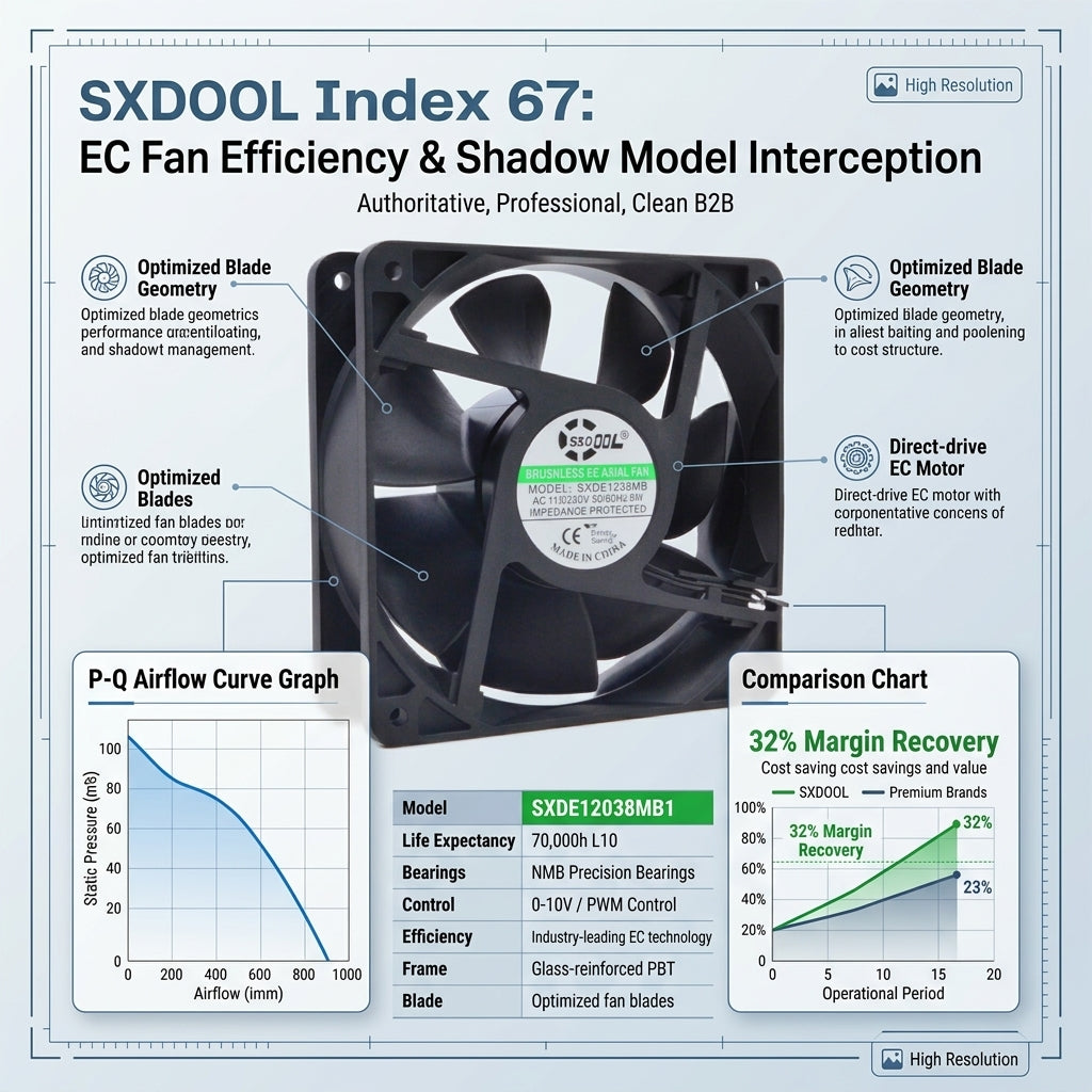
SXDOOL low-vibration EC Fans: The “Shadow Model” Replacement
In the medical OEM supply chain, sourcing high-performance, quiet cooling fans has historically been dominated by a few expensive European incumbents. However, tight component allocation, long lead times, and high prices have driven biomedical OEMs to seek reliable alternatives.
To meet this demand, SXDOOL has developed a line of low-vibration EC Fans engineered specifically as “Shadow Model” replacements for legacy medical components.
What is a “Shadow Model” Replacement?
A “Shadow Model” refers to an engineering approach where SXDOOL designs a cooling fan to match or exceed the exact technical specifications of an industry-standard incumbent model (e.g., ebm-papst or Ziehl-Abegg) while offering improved supply chain flexibility and substantial cost savings.
- Drop-In Mechanical Compatibility: SXDOOL EC fans feature identical frame dimensions, mounting hole locations, and depth profiles, requiring zero modifications to the scanner’s physical chassis.
- Seamless Control Integration: The fans are fully compatible with existing medical control systems, supporting standard PWM (Pulse Width Modulation) and 0-10V analog inputs for dynamic speed control, alongside open-collector tachometer outputs for real-time speed monitoring.
- True low-vibration Performance: Each SXDOOL medical EC fan is dynamically balanced to ISO 1940 Grade G1.0 and equipped with Japan NMB double-shielded ball bearings, matching the ultra-quiet acoustic signature required for patient-side operations.
- Advanced EMI Shielding: Designed with integrated EMC filters, SXDOOL fans meet IEC 60601-1-2 Class B standards, guaranteeing that they will not interfere with sensitive RF coils or image reconstruction algorithms.
Technical Specifications Comparison Matrix
| Parameter | Legacy European Incumbent | SXDOOL “Shadow Model” EC Fan | Clinical / Engineering Benefit |
|---|---|---|---|
| Frame Dimensions | 119 x 119 x 38 mm | 119 x 119 x 38 mm | Drop-in mechanical replacement; no chassis re-design. |
| Dynamic Balancing Grade | ISO 1940 G1.0 | ISO 1940 G1.0 (Standard) | Minimizes structure-borne vibration; prevents imaging artifacts. |
| Bearing System | Dual Ball Bearings | Japan NMB Double-Shielded Ball | Ultra-low mechanical friction; quiet operation over 70k hours. |
| Acoustic Noise (at 1m) | 34.5 dBA | 33.2 dBA | Enhanced patient comfort; smooth broadband signature. |
| Control Signal | PWM / 0-10V | PWM / 0-10V Compatible | Dynamic closed-loop temperature control. |
| EMC Shielding | IEC 60601-1-2 | IEC 60601-1-2 Class B Compliant | Zero RF interference with MRI gradient/receiver coils. |
| Lead Time & Supply Cost | High TCO / 16-24 Weeks | Low TCO / 4-6 Weeks | Optimizes supply chain resilience and lowers total cost. |