Power Supply Cooling Fans
Power Supply Cooling Fans for OEM Buyers
Choose power-supply and UPS cooling from conversion losses, the complete air path and the hottest component’s limit—not output watts alone. Compare normal and loaded-filter conditions, then confirm the fan supply, control interface and thermal result in the actual equipment.
SMPS & Rectifier Modules
Check hot spots around power semiconductors, magnetics and heat sinks. Restricted module vents can reduce installed airflow even when a fan has a high free-air rating.
UPS & Welding Power
Specify the UPS operating mode or welding duty cycle. Fan-on-demand control, contaminated air and filter loading change the cooling task; power-electronics cooling is separate from welding-fume extraction.
Information for Selection
Send measured or calculated power loss, inlet temperature, allowed component temperatures, airflow resistance, mounting envelope, actual fan supply, startup limit, connector and required control or alarm logic.
Where a fan belongs in a supply or UPS
A switch-mode supply needs cooling for losses in switching devices, magnetics, rectifiers and capacitors, not for its output wattage as such. Trace air from inlet to exhaust through heat sinks, grilles and a loaded filter; opposing system airflow can reduce cooling. A conduction-cooled supply may need no fan. For UPS modules, review charging, discharge and bypass conditions using the equipment maker’s loss and protection data. See TDK-Lambda’s power-supply airflow guidance for equipment-side design considerations; that source does not establish SXDOOL product performance.
Conditional SXDOOL sample path
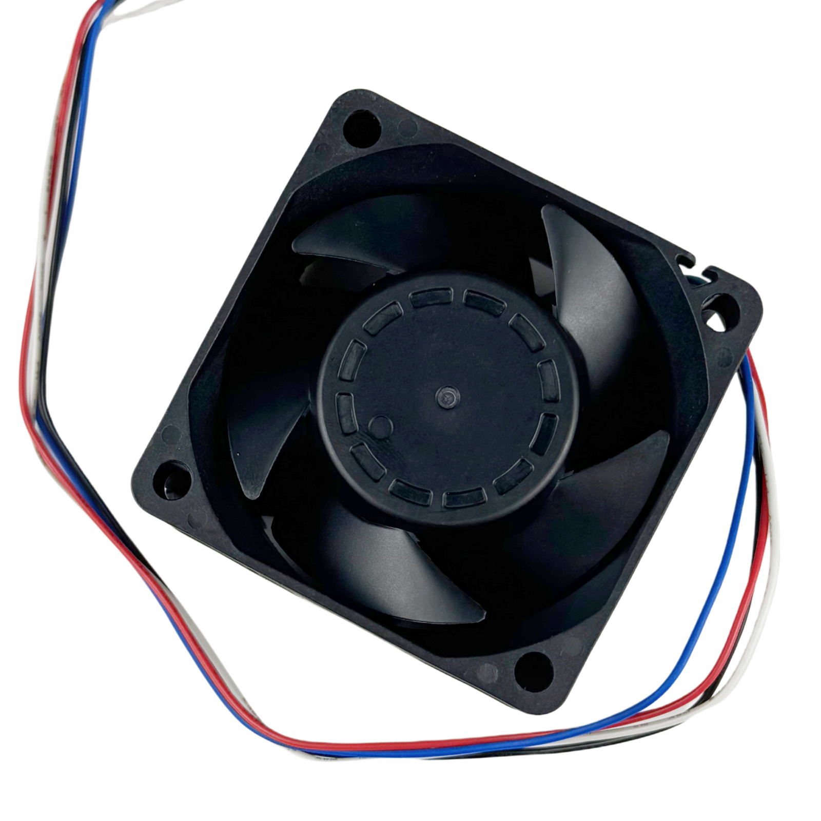
SXD6038B24H-RDP is a catalogued candidate for a document and sample review if the available space and electrical interface permit it. Request the current drawing, pressure–airflow curve and exact control or alarm definitions. The photographed SXD6038B24H sample is not proof of suitability for this supply or UPS; verify the ordered revision, startup budget, installed operating point, component temperatures and acoustics. Review the SXD6038B24H-RDP catalog listing and request exact-version technical documents before ordering a sample.
Can SXDOOL make high airflow power supply fans?
SXDOOL can review candidate platforms for these projects. Confirm the required installed duty point, space, supply and control interface, then validate the selected configuration in the equipment.
Does SXDOOL support custom connector power supply fans?
Yes. Connector, cable length, label, bearing, speed signal and packaging can be discussed during RFQ.
Application engineering
Power supply cooling fan selection for compact, high-density electronics
Engineering guide for power supply cooling
Drive airflow through heat sinks, magnetics and compact vents without exceeding the available fan depth. A reliable design starts with the heat load and the resistance of the complete airflow path. Free-air CFM is not enough when filters, heat sinks, grilles, ducts or densely packed components create pressure loss.
SXDOOL supports project review for switch-mode power supplies, UPS modules, battery chargers and industrial power units. The objective is to identify a suitable fan family and mounting envelope first, then confirm voltage, operating point, control signal, environment, cable, connector, documentation and sample requirements through RFQ.
| Primary engineering problem | Drive airflow through heat sinks, magnetics and compact vents without exceeding the available fan depth. |
|---|---|
| Candidate fan platforms | DC axial fans or centrifugal blowers, selected against the required duty point and mounting envelope. |
| Required project inputs | Conversion losses, component limits, fan cavity, exhaust restriction, voltage rail and target operating point. |
| Control and monitoring | PWM, FG and RD options should match the power supply controller and fault-handling strategy. |
| Environmental boundary | Check inlet contamination, orientation, start voltage and the system response to a stalled or disconnected fan. |
Power output is not the heat load
Start with loss data at the intended operating condition. For a steady-state converter, an initial estimate is output power multiplied by (1 / efficiency – 1), with efficiency expressed as a fraction. Include the relevant operating mode and other local losses; do not use the equipment nameplate output as the heat to remove. TDK-Lambda explains power-module thermal management.
Compare the installed duty point
A straight-through module may suit an axial candidate, while a turning outlet or restrictive path may justify a centrifugal candidate. Both need a matching pressure-flow curve, inlet clearance and thermal validation. Specify normal and loaded-filter conditions, acoustic limits and service access. A larger free-air CFM value does not establish better cooling inside the same enclosure.
Review control, monitoring and service
Confirm the fan supply independently of the power supply output. State whether the controller expects PWM, an FG speed output, an RD stall alarm or another defined interface; these are not interchangeable. Define safe equipment behavior when the fan stalls or is disconnected, and verify the bearing and life basis at the actual inlet temperature. For UPS, rectifier and welding projects, attach the equipment maker’s cooling and maintenance requirements.
Recommended selection sequence
- Quantify heat generation and the maximum allowable component or enclosure temperature.
- Map the inlet, outlet and internal obstructions, then estimate or measure the pressure drop at the target airflow.
- Confirm the available frame, depth, mounting pattern, supply voltage and controller signal interface.
- Review ambient temperature, dust, moisture, acoustic limits, service access, life expectation and fault response before approving samples.
power supply cooling FAQ
Which fan family should engineers start with for power supply cooling?
Compare DC axial fans and centrifugal blowers against the required duty point and mounting envelope. Start with the airflow path and system resistance, then check the available supply and control interface.
Which project data is required to size a fan for power supply cooling?
Conversion losses, component limits, fan cavity, exhaust restriction, voltage rail and target operating point. Include target temperature, mounting envelope and expected quantity so a duty point can be reviewed instead of selecting by fan diameter alone.
How should environmental and control requirements be specified for power supply cooling?
PWM, FG and RD options should match the power supply controller and fault-handling strategy. Check inlet contamination, orientation, start voltage and the system response to a stalled or disconnected fan.
Compare the available fan platforms, use the fan selector, review the related engineering resource, or email david@sxdool.com with the application data.