Inverter Cooling Fans for Power Electronics
Separate a VFD or servo drive’s heat-sink channel from cabinet and control-electronics airflow. Start with the exact drive manual, original fan label, heat losses and clearances; the drive’s mains rating does not identify the fan supply. Test any candidate in the intended duty and fault modes.
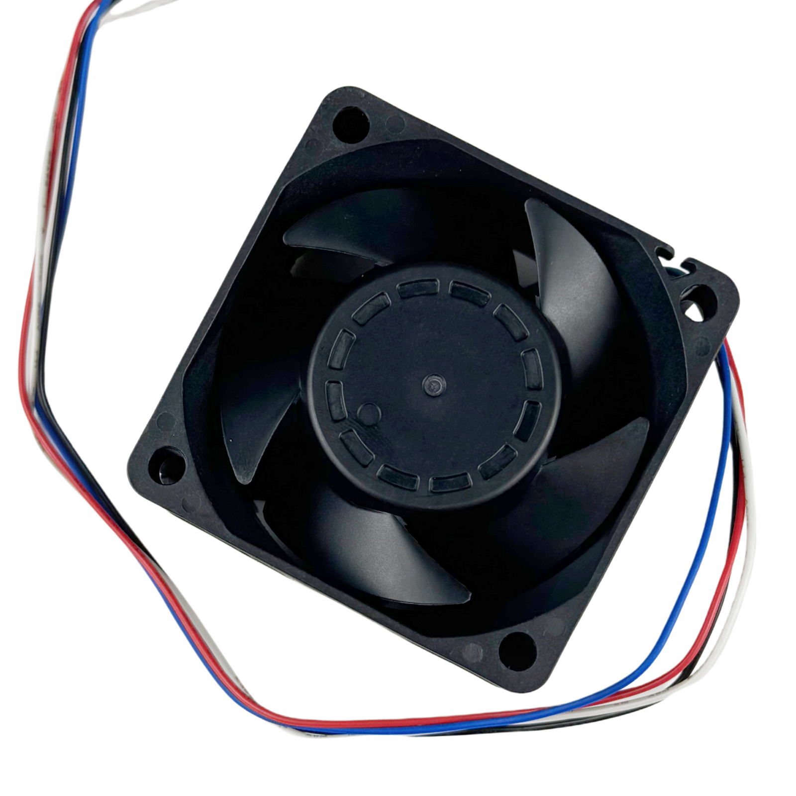
VFD Power Stages
Identify whether the fan cools a semiconductor heat sink, a separate cooling duct or the cabinet interior. Describe load, switching conditions, inlet temperature, altitude and the required derating limits.
Servo & Solar Equipment
Dense servo cabinets need clear spacing and a path for hot exhaust. Solar inverters may use passive or active cooling; shade, clearances and recirculation also affect temperature.
Replacement & Fault Monitoring
Read the exact fan label and equipment wiring diagram. Confirm supply range, pinout, startup current, speed-control input and fault response. Frame size and drive mains voltage do not establish compatibility.
Separate the drive’s cooling paths
A power-stage heat-sink duct, a cabinet exhaust and a control-electronics compartment can have different heat loads and resistance. Check inlet temperature, installation clearance, fouling, hot-air recirculation and derating in the exact drive manual. The mains rating and a 24 V control terminal do not establish the replacement fan supply; use the original fan label and wiring diagram. See Danfoss drive installation and cooling instructions for equipment-side design considerations; that source does not establish SXDOOL product performance.
Conditional SXDOOL sample path
SXD6038B24H-RDP is a catalogued model to investigate only if its envelope, supply and control interface fit the design. Request current pressure–airflow data and fault-signal definitions, then test the installed duty point, temperature and controller response during fan failure. Neither a VFD or servo-drive fit nor a reduction in thermal derating is established by the catalog link or photograph. Review the SXD6038B24H-RDP catalog listing and request exact-version technical documents before ordering a sample.
Can SXDOOL supply cooling fans for solar inverters?
SXDOOL can review DC, AC or EC candidates when their supply, pressure-flow curve, mounting and controller interface match the exact inverter. The equipment thermal test and required documentation determine approval.
Is SXDOOL suitable for small inverter fan custom orders?
Provide the sample, pilot and production quantities with the required configuration. Feasibility, minimum quantity and lead time are confirmed in the project quotation; production follows configuration and sample approval.
Application engineering
Inverter cooling fan selection for continuous-duty power electronics
Engineering guide for inverter cooling
Move heat away from switching devices and heat sinks across a restrictive internal airflow path. A reliable design starts with the heat load and the resistance of the complete airflow path. Free-air CFM is not enough when filters, heat sinks, grilles, ducts or densely packed components create pressure loss.
SXDOOL supports project review for solar inverters, motor drives, UPS systems and industrial power converters. The objective is to identify a suitable fan family and mounting envelope first, then confirm voltage, operating point, control signal, environment, cable, connector, documentation and sample requirements through RFQ.
| Primary engineering problem | Move heat away from switching devices and heat sinks across a restrictive internal airflow path. |
|---|---|
| Candidate fan platforms | DC axial fans for controlled low-voltage systems; EC or AC axial fans where mains input is preferred. |
| Required project inputs | Losses at rated load, heat-sink impedance, inlet temperature, altitude, airflow path and derating target. |
| Control and monitoring | PWM or EC speed control can track thermal load; FG/RD feedback supports fault monitoring. |
| Environmental boundary | Dust, conductive particles, humidity and expected continuous operating hours affect bearing and protection review. |
The drive voltage does not identify the fan voltage
A drive’s mains rating and its auxiliary control terminals do not establish the cooling fan supply. Check the exact equipment manual, original fan label and wiring diagram. Match voltage range, startup current, connector, pin assignment and signal logic before evaluating a replacement. Do not assume every industrial drive uses a 24 V fan.
Separate the heat-sink channel from cabinet airflow
A power-stage duct can have a different resistance and service path from the control-electronics compartment. Describe both air circuits, inlet and exhaust clearances, fouling and hot-air recirculation. Review the actual losses and operating conditions rather than motor output power alone. Solar-inverter equipment may use passive cooling, active cooling or a combination; a fan upgrade alone does not guarantee removal of thermal derating.
Verify the duty point and controller response
Compare axial and centrifugal candidates at the required airflow and pressure. Confirm speed-control input, whether monitoring requires rotation pulses or a stall alarm, fan-failure handling and installed acoustic limits. Dust, conductive particles, oil mist, humidity and service hours must be included in the configuration review.
Equipment references: Danfoss drive installation and cooling documentation; SMA inverter installation and heat dissipation. These explain review requirements; they do not approve an SXDOOL replacement.
Recommended selection sequence
- Quantify heat generation and the maximum allowable component or enclosure temperature.
- Map the inlet, outlet and internal obstructions, then estimate or measure the pressure drop at the target airflow.
- Confirm the available frame, depth, mounting pattern, supply voltage and controller signal interface.
- Review ambient temperature, dust, moisture, acoustic limits, service access, life expectation and fault response before approving samples.
inverter cooling FAQ
Which fan family should engineers start with for inverter cooling?
DC axial fans for controlled low-voltage systems; EC or AC axial fans where mains input is preferred. Start with the airflow path and system resistance, then compare the available frame, voltage and control interface.
Which project data is required to size a fan for inverter cooling?
Losses at rated load, heat-sink impedance, inlet temperature, altitude, airflow path and derating target. Include target temperature, mounting envelope and expected quantity so a duty point can be reviewed instead of selecting by fan diameter alone.
How should environmental and control requirements be specified for inverter cooling?
PWM or EC speed control can track thermal load; FG/RD feedback supports fault monitoring. Dust, conductive particles, humidity and expected continuous operating hours affect bearing and protection review.
Compare the available fan platforms, use the fan selector, review the related engineering resource, or email david@sxdool.com with the application data.